


User Manual
i Series / iX Series
53
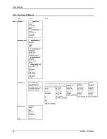
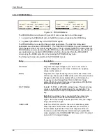
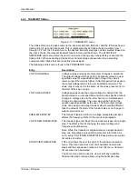
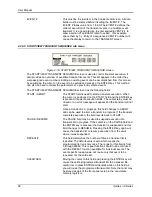
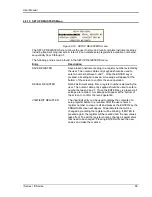
4.2.6 TRANSIENTS Menu
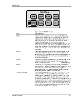
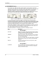
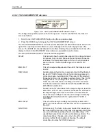
Figure 4-11: TRANSIENTS menu
The transient menu provides access to the transient list data. Both the i and the iX Series have a
transient list of up to 32 data points. This is represented by 32 transient step numbers from 1
through 32. From the Transient menu, the desired transient step type can be selected. Based on
the user‟s choice, the relevant transient type sub menu will be shown. The START/EDIT
SEQUENCE sub menu allows the user to review and change any transient step or execute the
transient list. When executing a transient list, transient steps are executed in a ascending
numerical order. Steps that are not defined are skipped.
The following entries can be found in the TRANSIENTS menu:
Entry
Description
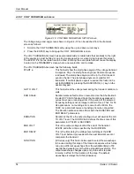
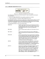
VOLT SURGE/SAG
Voltage surges and sags are temporary changes in amplitude.
The output voltage will change from its present value to a user
specified value for a specified duration. (Sag if the value is
lower, surge if the value is higher.) After this period has expired,
the output voltage returns to a user specified end value. This
value may or may not be the same as the value present prior to
the start of the sag or surge.
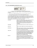
VOLT SWEEP/STEP
Voltage sweeps cause the output voltage to change from the
present value to a user specified end value at a specified rate of
change. A voltage step on the other hand is an instantaneous
change in output voltage. The new value will be held for the
duration period specified by the user. The final output voltage
value of a sweep and a step transient step should be different
than the value at the start of the transient step or no change in
output value will occur.
FREQ SWEEP/STEP
This transient type is similar to a voltage sweep/step except it
affects the frequency. Refer to the previous paragraph.
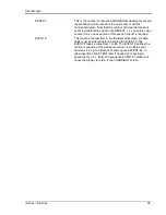
VOLT/FREQ SWEEP/STEP
This transient type combines the previous two types into a single
step. The effect is that of changing the output voltage and
frequency simultaneously.
Note: While this transient is programmed as a single transient
step, two list entries are required to store this information. As
such, every VOLT/FREQ SWEEP/STEP used will consume two
list entries at a time.
START/VIEW SEQUENCE
This entry allows the user to switch to the transient execution
menu. This menu provides a list of all available transient list
steps and their sequence numbers. From this menu, transient
list execution can be started.
The same menu can be used to view or edit any available
transient list step or erase a step using the backspace key.
Summary of Contents for 10001i
Page 2: ......
Page 3: ......
Page 6: ...ii This page intentionally left blank...
Page 38: ...User Manual 24 i Series iX Series Figure 3 5 Rear Panel View for the 3001i 3001iX...
Page 39: ...User Manual i Series iX Series 25 Figure 3 6 Rear Panel View for the 5001i 5001iX...
Page 43: ...User Manual i Series iX Series 29 Figure 3 8 Functional Test Setup...
Page 44: ...User Manual 30 i Series iX Series Figure 3 9 Single Phase 10000 VA System 10001iX i...
Page 46: ...User Manual 32 i Series iX Series Figure 3 11 Single Phase 15000 VA System 15001iX i...
Page 48: ...User Manual 34 i Series iX Series Figure 3 13 Connection With MODE Option...
Page 118: ...User Manual 104 i Series iX Series Figure 5 2 Power Source Module Block Diagram...
Page 121: ...User Manual i Series iX Series 107 Figure 5 3 5001i Internal Layout...
Page 122: ...User Manual 108 i Series iX Series Figure 5 4 Logic Board LED s...
Page 124: ...User Manual 110 i Series iX Series Figure 5 5 AC Power Stage Layout...
Page 125: ...User Manual i Series iX Series 111 Figure 5 6 AC Control Logic Block Diagram...
Page 138: ...User Manual 124 i Series iX Series Figure 6 3 Adjustment Location...
Page 152: ...User Manual 138 i Series iX Series Figure 9 4 Voltage Modulation...
Page 219: ...User Manual i Series iX Series 205 Figure 9 36 Example Connection With 5001iX and EOS 1...
Page 221: ...User Manual i Series iX Series 207 Figure 9 38 15003iX CTS EOS3 LR3...
Page 222: ...User Manual 208 i Series iX Series Figure 9 39 15003iX 3 EOS3...
Page 233: ...User Manual i Series iX Series 219 Figure 9 41 Example Connection With MODE iX...
Page 240: ...User Manual 226 i Series iX Series Figure 9 42 Example Connections With OMNI 1 18i...
Page 241: ...User Manual i Series iX Series 227 Figure 9 43 Example Connections With OMNI 3 18i...