User Manual
i Series / iX Series
89
4.6.3 Triggering Measurements
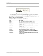
Both FFT results and waveform acquisitions may have to positioned at a specific moment in
time. To allow the data acquisition to coincide with user specified events, the measurement
system can be triggered in different ways. Trigger modes are available from both the bus and the
front panel. If the IEEE-488 or RS232C bus is used, acquisitions may also be triggered from the
transient list system. Refer to the programming manual for details on this mode of operation.
4.6.3.1 Trigger mode
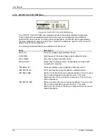
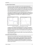
The following trigger modes are supported by the iX Series:
Single (SINGLE)
This mode causes the acquisition system to be armed only
once. The iX source waits for the user to press the ENTER key
while on the START field. As soon as the trigger event specified
occurs, data is acquired and the acquisition system is put in an
idle state. A new user initiated START event must be given to
trigger an new acquisition.
This mode is appropriate for capturing events that occur only
once such as the inrush current when turning on a load.
Continuous (CONT)
This mode causes the trigger system to re-arm itself after each
trigger event. Every time a new trigger event occurs, new data is
acquired and the LCD display is updated. No user intervention is
required after the initial START event.
This mode is appropriate for capturing repetitive events or to
monitor the source output continuously. Display updates will
occur about once per second.
4.6.3.2 Trigger source
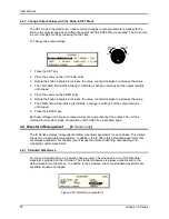
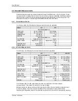
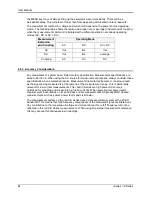
The iX Series offers a choice of trigger sources in front panel operation mode. The following
trigger sources are available from the HARMONICS/TRACE ANALYSIS, TRIG SOURCE field:
Immediate (IMM)
This mode causes a trigger to occur as soon as the ENTER key
is pressed with the cursor on the START field. No trigger source
needs to be specified for this trigger mode. This mode is
equivalent to the INIT:IMM:ACQ bus command.
This trigger source is appropriate if no trigger condition is known
or desired. When using this trigger source, the acquisition is
always triggered.
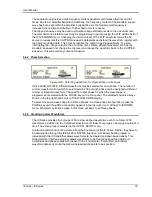
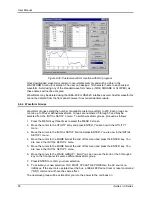
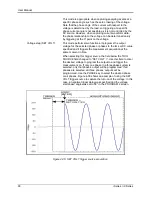
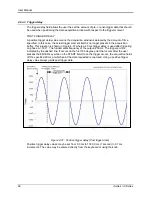
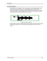
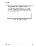
Phase (PHASE A)
This mode causes the iX acquisition system to wait for a
specified phase angle on the phase A voltage output. This
allows the acquisition to be positioned in time with respect to
any phase angle on phase A, B or C. Note that phase A, B and
C are typically at 0°, 240° and 120° with respect to the specified
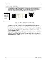
trigger phase in this field. An example of this trigger source
mode is shown in Figure 4-37.
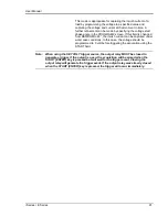
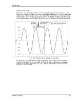
When selecting this trigger source, the field below the TRIG
SOURCE f
ield changed to “TRIG PHASE =“. Use this field to
enter the desired voltage phase angle to trigger the
measurement on.
Summary of Contents for 10001i
Page 2: ......
Page 3: ......
Page 6: ...ii This page intentionally left blank...
Page 38: ...User Manual 24 i Series iX Series Figure 3 5 Rear Panel View for the 3001i 3001iX...
Page 39: ...User Manual i Series iX Series 25 Figure 3 6 Rear Panel View for the 5001i 5001iX...
Page 43: ...User Manual i Series iX Series 29 Figure 3 8 Functional Test Setup...
Page 44: ...User Manual 30 i Series iX Series Figure 3 9 Single Phase 10000 VA System 10001iX i...
Page 46: ...User Manual 32 i Series iX Series Figure 3 11 Single Phase 15000 VA System 15001iX i...
Page 48: ...User Manual 34 i Series iX Series Figure 3 13 Connection With MODE Option...
Page 118: ...User Manual 104 i Series iX Series Figure 5 2 Power Source Module Block Diagram...
Page 121: ...User Manual i Series iX Series 107 Figure 5 3 5001i Internal Layout...
Page 122: ...User Manual 108 i Series iX Series Figure 5 4 Logic Board LED s...
Page 124: ...User Manual 110 i Series iX Series Figure 5 5 AC Power Stage Layout...
Page 125: ...User Manual i Series iX Series 111 Figure 5 6 AC Control Logic Block Diagram...
Page 138: ...User Manual 124 i Series iX Series Figure 6 3 Adjustment Location...
Page 152: ...User Manual 138 i Series iX Series Figure 9 4 Voltage Modulation...
Page 219: ...User Manual i Series iX Series 205 Figure 9 36 Example Connection With 5001iX and EOS 1...
Page 221: ...User Manual i Series iX Series 207 Figure 9 38 15003iX CTS EOS3 LR3...
Page 222: ...User Manual 208 i Series iX Series Figure 9 39 15003iX 3 EOS3...
Page 233: ...User Manual i Series iX Series 219 Figure 9 41 Example Connection With MODE iX...
Page 240: ...User Manual 226 i Series iX Series Figure 9 42 Example Connections With OMNI 1 18i...
Page 241: ...User Manual i Series iX Series 227 Figure 9 43 Example Connections With OMNI 3 18i...

