


User Manual
238
i Series / iX Series
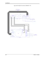
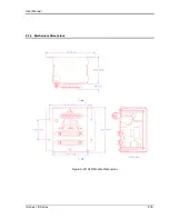
9.7.6 Installation
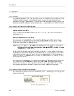
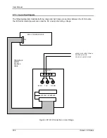
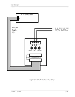
The XLS module can be installed inside a system cabinet or other vertical structure in the vicinity
of the iX power source. Refer to Figure 9-50 and Figure 9-51 for connection details. The input
voltage can be applied to the AC input terminal strip as shown, or, banana jacks can be used to
secure the line voltage to the XLS module. The system interface ribbon cable can be connected
to either of the two connectors on the XLS module. The extra connector is provided for pass-
through connectivity.
9.7.7 XLS Option Operation
The External Line Sync option (XLS) allows the output of the i/iX AC Source to be synchronized
to any line input, whether it is the line powering the iX source or any other line voltage not
necessarily hooked up to the iX source. This capability may be needed to support tests that
require the use of additional equipment.
The XLS Option
– once installed and connected – can be turned on from the iX front panel as
follows:
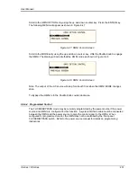
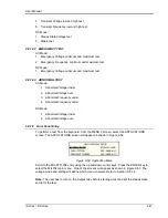
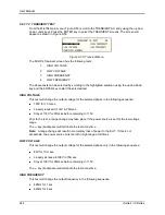
Select the PROGRAM 2 screen and move the cursor to the CLK MODE field. The default value
for the field is INT for internal clock mode. Use the knob to select the SYNC mode in order to
enable the XLS. If the XLS is not installed a “LINE SYNC ERROR” will appear after a short
period in the top left of the screen. This means the XLS option is either not present or not
receiving a phase input signal from the line.
To turn the sync mode back off, set the CLK MODE field back to INT.
Over the bus, the XLS is enabled or disabled as follows:
FREQ:MODE SENS
/* Enables XLS */
FREQ:MODE FIX
/* Disables XLS */
If the XLS is not installed and the FREQ:MODE SENS command is issued, an error message is
generated. If done as part of a test program, an error check should be done after a 800 msec
delay to allow the i/iX to sense the presence of a sync signal coming from the XLS module. If no
error occurs, the XLS is active. If an error occurs, the XLS may not be available or not
functioning and the mode has reverted back to internal.
The XLS option is designed to keep the iX output frequency locked to the line frequency. There is
a finite phase offset however, between the iX source output and the line input to the External
Sync Module. This phase offset will vary somewhat with the line voltage going to the XLS
module. If it is desired to have the iX output in phase with the line input, it will be necessary to
monitor the iX output voltage as well as the line input to the XLS module using a two channel
oscilloscope to compare the zero-crossings of the voltage waveforms. An isolation amplifier must
be used when connecting the sync input line to the o‟scope input. To program an offset angle on
the iX source, go to PROGRAM 2 screen and select PHASE. Typically 25-30 of phase angle will
put the line input and the source output in-phase, but the exact angle to program can only be
determined by monitoring the iX source and the line input voltage and comparing the waveforms.
Summary of Contents for 10001i
Page 2: ......
Page 3: ......
Page 6: ...ii This page intentionally left blank...
Page 38: ...User Manual 24 i Series iX Series Figure 3 5 Rear Panel View for the 3001i 3001iX...
Page 39: ...User Manual i Series iX Series 25 Figure 3 6 Rear Panel View for the 5001i 5001iX...
Page 43: ...User Manual i Series iX Series 29 Figure 3 8 Functional Test Setup...
Page 44: ...User Manual 30 i Series iX Series Figure 3 9 Single Phase 10000 VA System 10001iX i...
Page 46: ...User Manual 32 i Series iX Series Figure 3 11 Single Phase 15000 VA System 15001iX i...
Page 48: ...User Manual 34 i Series iX Series Figure 3 13 Connection With MODE Option...
Page 118: ...User Manual 104 i Series iX Series Figure 5 2 Power Source Module Block Diagram...
Page 121: ...User Manual i Series iX Series 107 Figure 5 3 5001i Internal Layout...
Page 122: ...User Manual 108 i Series iX Series Figure 5 4 Logic Board LED s...
Page 124: ...User Manual 110 i Series iX Series Figure 5 5 AC Power Stage Layout...
Page 125: ...User Manual i Series iX Series 111 Figure 5 6 AC Control Logic Block Diagram...
Page 138: ...User Manual 124 i Series iX Series Figure 6 3 Adjustment Location...
Page 152: ...User Manual 138 i Series iX Series Figure 9 4 Voltage Modulation...
Page 219: ...User Manual i Series iX Series 205 Figure 9 36 Example Connection With 5001iX and EOS 1...
Page 221: ...User Manual i Series iX Series 207 Figure 9 38 15003iX CTS EOS3 LR3...
Page 222: ...User Manual 208 i Series iX Series Figure 9 39 15003iX 3 EOS3...
Page 233: ...User Manual i Series iX Series 219 Figure 9 41 Example Connection With MODE iX...
Page 240: ...User Manual 226 i Series iX Series Figure 9 42 Example Connections With OMNI 1 18i...
Page 241: ...User Manual i Series iX Series 227 Figure 9 43 Example Connections With OMNI 3 18i...