User Manual
222
i Series / iX Series
9.6 Omni Options
9.6.1 Introduction
This section contains information on the installation and operation of the OMNI (Output Matching
Network Impedance) impedance network to be used with the California Instruments
i-or iX-series of power sources.
9.6.2 General Description
The OMNI impedance network adds inductive and resistive impedance to California Instruments
i-or iX-series power sources. This additional impedance brings the combined system impedance
up to the levels required of the power source for IEC 555-3 and IEC 1000-3-3 (flicker) testing.
9.6.3 Specifications
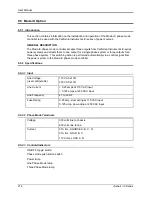
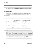
9.6.3.1 Input
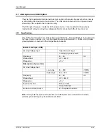
Omni 1-18i and 3-18i
Omni 1-37i, 1-37iJ and 3-37i
Line Voltage
(user configurable)
115 VAC ±10% or
230 VAC ±10%
115 VAC ±10% or
230 VAC ±10%
Line Current
< 0.25 amps at 115 VAC input
< 0.125 amps at 230 VAC input
< 1.0 amps at 115 VAC input
< 0.5 amps at 230 VAC input
Line Frequency
47 to 63 Hz
47 to 63 Hz
Fuse Rating
0.25 amp, slow acting at 115 VAC input
0.125 amp, slow acting at 230 VAC
input
2 Amp, slow acting used for
both input ranges
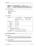
9.6.3.2 Output
OMNI Type
1-18i
3-18i
1-37i and 1-37iJ
3-37i
Phases
1
3
1
3
Current max, rms.
18.5A per phase
18.5A per phase
37A per phase
37A per phase
Current in bypass
37A per phase
37A per phase
74A per phase
74A per phase
NOTE: To prevent damage to the OMNI unit , the BYPASS mode must be
selected when the power source is operated on low output voltage range
or if currents in excess of OMNI ratings will be drawn.
Summary of Contents for 10001i
Page 2: ......
Page 3: ......
Page 6: ...ii This page intentionally left blank...
Page 38: ...User Manual 24 i Series iX Series Figure 3 5 Rear Panel View for the 3001i 3001iX...
Page 39: ...User Manual i Series iX Series 25 Figure 3 6 Rear Panel View for the 5001i 5001iX...
Page 43: ...User Manual i Series iX Series 29 Figure 3 8 Functional Test Setup...
Page 44: ...User Manual 30 i Series iX Series Figure 3 9 Single Phase 10000 VA System 10001iX i...
Page 46: ...User Manual 32 i Series iX Series Figure 3 11 Single Phase 15000 VA System 15001iX i...
Page 48: ...User Manual 34 i Series iX Series Figure 3 13 Connection With MODE Option...
Page 118: ...User Manual 104 i Series iX Series Figure 5 2 Power Source Module Block Diagram...
Page 121: ...User Manual i Series iX Series 107 Figure 5 3 5001i Internal Layout...
Page 122: ...User Manual 108 i Series iX Series Figure 5 4 Logic Board LED s...
Page 124: ...User Manual 110 i Series iX Series Figure 5 5 AC Power Stage Layout...
Page 125: ...User Manual i Series iX Series 111 Figure 5 6 AC Control Logic Block Diagram...
Page 138: ...User Manual 124 i Series iX Series Figure 6 3 Adjustment Location...
Page 152: ...User Manual 138 i Series iX Series Figure 9 4 Voltage Modulation...
Page 219: ...User Manual i Series iX Series 205 Figure 9 36 Example Connection With 5001iX and EOS 1...
Page 221: ...User Manual i Series iX Series 207 Figure 9 38 15003iX CTS EOS3 LR3...
Page 222: ...User Manual 208 i Series iX Series Figure 9 39 15003iX 3 EOS3...
Page 233: ...User Manual i Series iX Series 219 Figure 9 41 Example Connection With MODE iX...
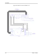
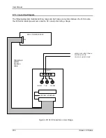
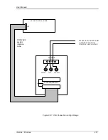
Page 240: ...User Manual 226 i Series iX Series Figure 9 42 Example Connections With OMNI 1 18i...
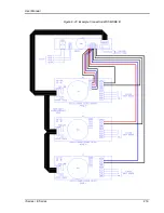
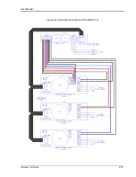
Page 241: ...User Manual i Series iX Series 227 Figure 9 43 Example Connections With OMNI 3 18i...


