


User Manual
204
i Series / iX Series
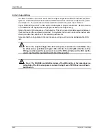
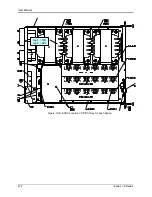
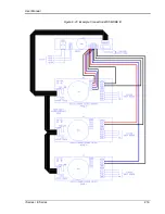
9.4.5.4 Output Wiring
The EOS-1 or EOS-3 is wired in series with the output of specified California Instruments power
systems. The EOS terminal block marked SOURCE should be wired to the output of the power
source/system. The terminal block marked LOAD is wired to the user's load. Refer to
Figure 9-36 and Figure 9-37 in this section for examples of proper connections. Refer to Section
3.5 to determine the appropriate wire gauge needed for the output wiring.
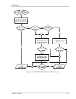
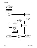
Note in Figure 9-36 the sequence of instruments. This is the recommended sequence between
the iX source and the equipment under test. For systems that do not include all the instruments
shown, maintain the sequence of the remaining instruments.
Note also that for all applications the remote sense wiring must be connected
before
the EOS
unit.
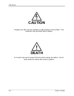
Note: The output voltage of the iX/i-series power sources into the EOS box may
be at hazardous potentials as high as 300 volts line to neutral (600 volts line to line).
Wiring used between the power sources and the EOS and between the EOS and the
user’s load must be insulated to withstand this potential.
Note: The SOURCE and LOAD terminals of the EOS will be at the hazardous live
potentials of the iX/i-series power sources driving it even if EOS box has not been
switched on.
Summary of Contents for 10001i
Page 2: ......
Page 3: ......
Page 6: ...ii This page intentionally left blank...
Page 38: ...User Manual 24 i Series iX Series Figure 3 5 Rear Panel View for the 3001i 3001iX...
Page 39: ...User Manual i Series iX Series 25 Figure 3 6 Rear Panel View for the 5001i 5001iX...
Page 43: ...User Manual i Series iX Series 29 Figure 3 8 Functional Test Setup...
Page 44: ...User Manual 30 i Series iX Series Figure 3 9 Single Phase 10000 VA System 10001iX i...
Page 46: ...User Manual 32 i Series iX Series Figure 3 11 Single Phase 15000 VA System 15001iX i...
Page 48: ...User Manual 34 i Series iX Series Figure 3 13 Connection With MODE Option...
Page 118: ...User Manual 104 i Series iX Series Figure 5 2 Power Source Module Block Diagram...
Page 121: ...User Manual i Series iX Series 107 Figure 5 3 5001i Internal Layout...
Page 122: ...User Manual 108 i Series iX Series Figure 5 4 Logic Board LED s...
Page 124: ...User Manual 110 i Series iX Series Figure 5 5 AC Power Stage Layout...
Page 125: ...User Manual i Series iX Series 111 Figure 5 6 AC Control Logic Block Diagram...
Page 138: ...User Manual 124 i Series iX Series Figure 6 3 Adjustment Location...
Page 152: ...User Manual 138 i Series iX Series Figure 9 4 Voltage Modulation...
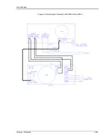
Page 219: ...User Manual i Series iX Series 205 Figure 9 36 Example Connection With 5001iX and EOS 1...
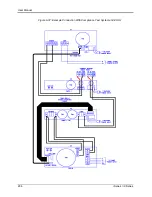
Page 221: ...User Manual i Series iX Series 207 Figure 9 38 15003iX CTS EOS3 LR3...
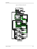
Page 222: ...User Manual 208 i Series iX Series Figure 9 39 15003iX 3 EOS3...
Page 233: ...User Manual i Series iX Series 219 Figure 9 41 Example Connection With MODE iX...
Page 240: ...User Manual 226 i Series iX Series Figure 9 42 Example Connections With OMNI 1 18i...
Page 241: ...User Manual i Series iX Series 227 Figure 9 43 Example Connections With OMNI 3 18i...