

User Manual
126
i Series / iX Series
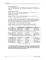
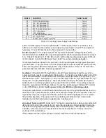
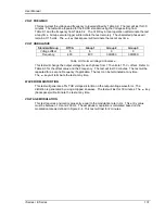
7.3.4 Distorted Output
CAUSE
SOLUTION
Power source is grossly overloaded.
Reduce load
The crest factor of the load exceeds 3:1 on
the low range or 5:1 on the high range.
Reduce load current peaks by reducing
load.
7.3.5 Unit Shuts Down after 1-2 Seconds
CAUSE
SOLUTION
Output shorted
Remove output short
Output grossly overloaded.
Remove overload.
Operating load with too high inrush or start
up currents.
Consult factory for application advice.
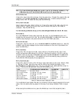
7.3.6 No Output and No Lights on Front Panel
CAUSE
SOLUTION
Input circuit breaker switched off.
Switch the breaker on.
No input power to TB3.
Ensure 3 phase power is getting to TB3.
Unit tripped on overvoltage or overcurrent.
Turn circuit breaker off - wait five seconds
- turn circuit breaker back on.
7.3.7
No Output But “Power On” LED on Front Panel is Lit
CAUSE
SOLUTION
“OUTPUT ON” switch is turned off.
Turn OUTPUT ON switch to “ON”.
REMOTE SHUTDOWN logic line at J22
pin 36 is shorted to D COM or A COM.
Remove connection from J22 pin 3.
Current limit programmed down or to zero.
Program current limit higher.
Voltage programmed down or to zero.
Turn amplitude control up.
Unit tripped on overvoltage or overcurrent. Turn circuit breaker off - wait five seconds
- turn circuit breaker back on.
Summary of Contents for 10001i
Page 2: ......
Page 3: ......
Page 6: ...ii This page intentionally left blank...
Page 38: ...User Manual 24 i Series iX Series Figure 3 5 Rear Panel View for the 3001i 3001iX...
Page 39: ...User Manual i Series iX Series 25 Figure 3 6 Rear Panel View for the 5001i 5001iX...
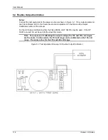
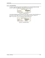
Page 43: ...User Manual i Series iX Series 29 Figure 3 8 Functional Test Setup...
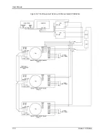
Page 44: ...User Manual 30 i Series iX Series Figure 3 9 Single Phase 10000 VA System 10001iX i...
Page 46: ...User Manual 32 i Series iX Series Figure 3 11 Single Phase 15000 VA System 15001iX i...
Page 48: ...User Manual 34 i Series iX Series Figure 3 13 Connection With MODE Option...
Page 118: ...User Manual 104 i Series iX Series Figure 5 2 Power Source Module Block Diagram...
Page 121: ...User Manual i Series iX Series 107 Figure 5 3 5001i Internal Layout...
Page 122: ...User Manual 108 i Series iX Series Figure 5 4 Logic Board LED s...
Page 124: ...User Manual 110 i Series iX Series Figure 5 5 AC Power Stage Layout...
Page 125: ...User Manual i Series iX Series 111 Figure 5 6 AC Control Logic Block Diagram...
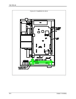
Page 138: ...User Manual 124 i Series iX Series Figure 6 3 Adjustment Location...
Page 152: ...User Manual 138 i Series iX Series Figure 9 4 Voltage Modulation...
Page 219: ...User Manual i Series iX Series 205 Figure 9 36 Example Connection With 5001iX and EOS 1...
Page 221: ...User Manual i Series iX Series 207 Figure 9 38 15003iX CTS EOS3 LR3...
Page 222: ...User Manual 208 i Series iX Series Figure 9 39 15003iX 3 EOS3...
Page 233: ...User Manual i Series iX Series 219 Figure 9 41 Example Connection With MODE iX...
Page 240: ...User Manual 226 i Series iX Series Figure 9 42 Example Connections With OMNI 1 18i...
Page 241: ...User Manual i Series iX Series 227 Figure 9 43 Example Connections With OMNI 3 18i...