


User Manual
16
i Series / iX Series
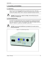
3.3 Mechanical Installation
The 3001i/iX and 5001i/iX are completely self contained power sources. They may be used free
standing on a bench top or rack mounted using the optional rack mount/handle kit. The units are
fan cooled, drawing air in from the sides and exhausting at the rear. The sides of each unit must
be kept clear of obstruction and a 6” clearance must be maintained to the rear. Special
consideration of overall air flow characteristics and the resultant internal heat rise must be
allowed for with systems installed inside enclosed cabinets to avoid self heating and over
temperature problems.
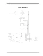
3.4 Input Wiring
– TB1
The input terminal block, TB1, is located at the rear of the unit. Ground (earth) wire must be
connected to the chassis of the AC power system. The mains source must have a current rating
equal to or greater than the input circuit breaker and the input wiring must be sized to satisfy the
applicable electrical codes. The input terminal block cover and strain relief must be installed in
table top applications to maintain protection against hazardous voltages.
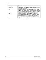
CAUTION: Capacitors in the power source may hold a hazardous electrical charge
even if the power source has been disconnected from the mains supply. Allow
capacitors to discharge to a safe voltage before touching exposed pins of mains
supply connectors.
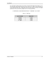
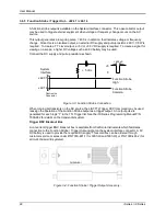
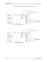
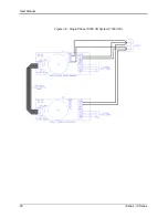
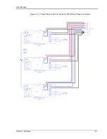
3.5 Output Power Connections
– TB2
The output terminal block, TB2, is located at the rear of the unit. The external sense inputs allow
the power system output voltages to be monitored directly at the load and must be connected
either at TB2 or the load
when the sense is programmed for external. The external sense input
does not have to be connected when Internal Sense is programmed. The external sense wires
are to be connected to TB3 on the rear panel and should be run as a twisted pair for short
lengths. Sense leads over three (3) feet long should be run as a twisted shielded pair. Refer to
Figures 3-2 through 3-12 for all connections.
Note: The output of the power source is isolated from the input line and floating from
chassis ground. If needed, either side (HI or LO) may be grounded.
Summary of Contents for 10001i
Page 2: ......
Page 3: ......
Page 6: ...ii This page intentionally left blank...
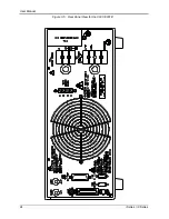
Page 38: ...User Manual 24 i Series iX Series Figure 3 5 Rear Panel View for the 3001i 3001iX...
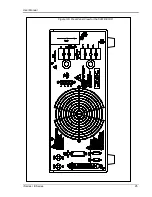
Page 39: ...User Manual i Series iX Series 25 Figure 3 6 Rear Panel View for the 5001i 5001iX...
Page 43: ...User Manual i Series iX Series 29 Figure 3 8 Functional Test Setup...
Page 44: ...User Manual 30 i Series iX Series Figure 3 9 Single Phase 10000 VA System 10001iX i...
Page 46: ...User Manual 32 i Series iX Series Figure 3 11 Single Phase 15000 VA System 15001iX i...
Page 48: ...User Manual 34 i Series iX Series Figure 3 13 Connection With MODE Option...
Page 118: ...User Manual 104 i Series iX Series Figure 5 2 Power Source Module Block Diagram...
Page 121: ...User Manual i Series iX Series 107 Figure 5 3 5001i Internal Layout...
Page 122: ...User Manual 108 i Series iX Series Figure 5 4 Logic Board LED s...
Page 124: ...User Manual 110 i Series iX Series Figure 5 5 AC Power Stage Layout...
Page 125: ...User Manual i Series iX Series 111 Figure 5 6 AC Control Logic Block Diagram...
Page 138: ...User Manual 124 i Series iX Series Figure 6 3 Adjustment Location...
Page 152: ...User Manual 138 i Series iX Series Figure 9 4 Voltage Modulation...
Page 219: ...User Manual i Series iX Series 205 Figure 9 36 Example Connection With 5001iX and EOS 1...
Page 221: ...User Manual i Series iX Series 207 Figure 9 38 15003iX CTS EOS3 LR3...
Page 222: ...User Manual 208 i Series iX Series Figure 9 39 15003iX 3 EOS3...
Page 233: ...User Manual i Series iX Series 219 Figure 9 41 Example Connection With MODE iX...
Page 240: ...User Manual 226 i Series iX Series Figure 9 42 Example Connections With OMNI 1 18i...
Page 241: ...User Manual i Series iX Series 227 Figure 9 43 Example Connections With OMNI 3 18i...


