User Manual
68
i Series / iX Series
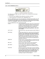
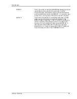
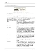
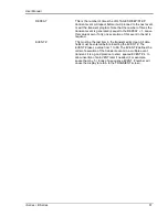
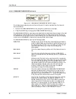
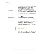
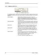
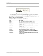
4.2.11.1 GPIB/RS232 SETUP menu
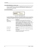
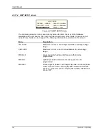
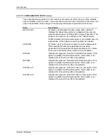
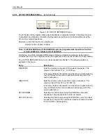
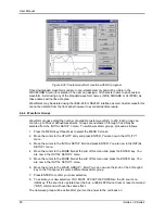
Figure 4-21: GPIB/RS232 SETUP menu
The GPIB/RS232 SETUP menu may be used to change the interface parameter settings for both
the IEEE-488 interface and the RS232 serial interface. The following parameters can be set from
this menu:
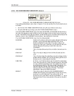
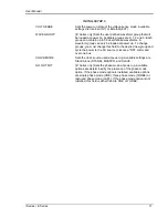
GPIB ADDRESS
Sets the IEEE-488 address used by the AC source. The
address value can be set from 0 through 31. Address 0 is often
reserved for the IEEE-488 controller. The factory setting is
address 1. Once changed, the IEEE-488 address is retained in
nonvolatile memory.
RS232 BAUDRATE
This field can be used to set the RS232 baudrate to either 9600,
19200 or 38400 baud. The baudrate set on the AC source must
match the one programmed for the communications port of the
controller.
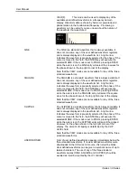
RS232 DATA
This field is used to set the number of databits to either 7 or 8.
Factory setting is 8 bits. This value must match the number of
data bits set on the communications port of the controller.
RS232 PARITY
This field is used to set the parity. Available options are Even
(E), Odd (O) or no parity (N). Factory setting is No parity. This
value must match the parity set on the communications port of
the controller.
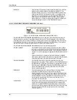
RS232 STPBITS
This field is used to set the number of stop bits used on the
serial port. Available options are 1 or 2 bits. Factory setting is 1
stop bit. This value must match the parity set on the
communications port of the controller.
The number of start bits is always fiXed to 1 bit.
Summary of Contents for 10001i
Page 2: ......
Page 3: ......
Page 6: ...ii This page intentionally left blank...
Page 38: ...User Manual 24 i Series iX Series Figure 3 5 Rear Panel View for the 3001i 3001iX...
Page 39: ...User Manual i Series iX Series 25 Figure 3 6 Rear Panel View for the 5001i 5001iX...
Page 43: ...User Manual i Series iX Series 29 Figure 3 8 Functional Test Setup...
Page 44: ...User Manual 30 i Series iX Series Figure 3 9 Single Phase 10000 VA System 10001iX i...
Page 46: ...User Manual 32 i Series iX Series Figure 3 11 Single Phase 15000 VA System 15001iX i...
Page 48: ...User Manual 34 i Series iX Series Figure 3 13 Connection With MODE Option...
Page 118: ...User Manual 104 i Series iX Series Figure 5 2 Power Source Module Block Diagram...
Page 121: ...User Manual i Series iX Series 107 Figure 5 3 5001i Internal Layout...
Page 122: ...User Manual 108 i Series iX Series Figure 5 4 Logic Board LED s...
Page 124: ...User Manual 110 i Series iX Series Figure 5 5 AC Power Stage Layout...
Page 125: ...User Manual i Series iX Series 111 Figure 5 6 AC Control Logic Block Diagram...
Page 138: ...User Manual 124 i Series iX Series Figure 6 3 Adjustment Location...
Page 152: ...User Manual 138 i Series iX Series Figure 9 4 Voltage Modulation...
Page 219: ...User Manual i Series iX Series 205 Figure 9 36 Example Connection With 5001iX and EOS 1...
Page 221: ...User Manual i Series iX Series 207 Figure 9 38 15003iX CTS EOS3 LR3...
Page 222: ...User Manual 208 i Series iX Series Figure 9 39 15003iX 3 EOS3...
Page 233: ...User Manual i Series iX Series 219 Figure 9 41 Example Connection With MODE iX...
Page 240: ...User Manual 226 i Series iX Series Figure 9 42 Example Connections With OMNI 1 18i...
Page 241: ...User Manual i Series iX Series 227 Figure 9 43 Example Connections With OMNI 3 18i...

