User Manual
102
i Series / iX Series
5.2 Overall Description
Three or single phase input power is routed in from the back panel through an EMI filter and the
circuit breaker to the input bridge rectifier. The DC output from the bridge rectifier is smoothed
by a small amount of capacitance in order to keep the input power factor as high as possible.
This DC output supplies the converter on the DC power board.
The DC converter turns the unregulated rectified AC into a smoothed, isolated, tightly regulated
DC supply. Also mounted on the DC power board is the auxiliary power supply. The auxiliary
power supply creates low voltages to operate the control logic board, the oscillator board, the AC
power board, and the fan. The output of the DC converter is fed to two large electrolytic
capacitors on the I/O board. These capacitors also provide holdover storage energy to ride
through line dropouts.
The AC power board takes the DC input and puts out isolated, direct coupled, AC power.
The DC bus is regulated at 250 volts for the 135/150 VAC output and 500 volts for the 270/300
VAC output.
The oscillator assembly generates the reference waveforms and provides frequency, amplitude,
and impedance control. The current limit board, in conjunction with the oscillator board, provides
the current limit function.
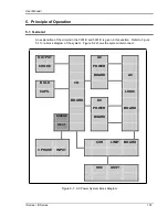
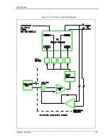
The assemblies are described in more detail in the following paragraphs. Refer to Figure 5-1 for
an overall block diagram.
5.3 Oscillator Assembly
The oscillator assembly consists of three printed circuit board assemblies connected by a ribbon
cable. The oscillator generates the sine wave signal setting the frequency, amplitude and current
limit level. It also senses the output voltage to provide closed loop control of the output.
5.3.1 CPU/Phase A Board
This board assembly, A7, consists of the components for the DSP, generating the input signal for
the power amplifier, programmable impedance and all of the memory. In addition, the waveform
board contains the circuits for all measurements and remote sense. The clock and lock circuit
for 3-phase operation is also on this board assembly.
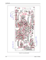
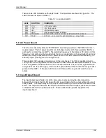
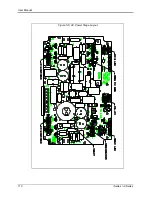
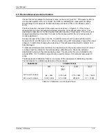
This board has several jumpers that are used to enable various option. Refer to the following
table for the options. See Figure 5-2.
JUMPER ( += in, - = out)
W3
W4
W5
W6
W7
W8
W9
Standard, CLK & LK
Master
-
+
+
-
+
-
+
CLK & LK Slave
+
-
-
+
-
+
-
Summary of Contents for 10001i
Page 2: ......
Page 3: ......
Page 6: ...ii This page intentionally left blank...
Page 38: ...User Manual 24 i Series iX Series Figure 3 5 Rear Panel View for the 3001i 3001iX...
Page 39: ...User Manual i Series iX Series 25 Figure 3 6 Rear Panel View for the 5001i 5001iX...
Page 43: ...User Manual i Series iX Series 29 Figure 3 8 Functional Test Setup...
Page 44: ...User Manual 30 i Series iX Series Figure 3 9 Single Phase 10000 VA System 10001iX i...
Page 46: ...User Manual 32 i Series iX Series Figure 3 11 Single Phase 15000 VA System 15001iX i...
Page 48: ...User Manual 34 i Series iX Series Figure 3 13 Connection With MODE Option...
Page 118: ...User Manual 104 i Series iX Series Figure 5 2 Power Source Module Block Diagram...
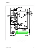
Page 121: ...User Manual i Series iX Series 107 Figure 5 3 5001i Internal Layout...
Page 122: ...User Manual 108 i Series iX Series Figure 5 4 Logic Board LED s...
Page 124: ...User Manual 110 i Series iX Series Figure 5 5 AC Power Stage Layout...
Page 125: ...User Manual i Series iX Series 111 Figure 5 6 AC Control Logic Block Diagram...
Page 138: ...User Manual 124 i Series iX Series Figure 6 3 Adjustment Location...
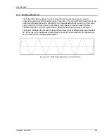
Page 152: ...User Manual 138 i Series iX Series Figure 9 4 Voltage Modulation...
Page 219: ...User Manual i Series iX Series 205 Figure 9 36 Example Connection With 5001iX and EOS 1...
Page 221: ...User Manual i Series iX Series 207 Figure 9 38 15003iX CTS EOS3 LR3...
Page 222: ...User Manual 208 i Series iX Series Figure 9 39 15003iX 3 EOS3...
Page 233: ...User Manual i Series iX Series 219 Figure 9 41 Example Connection With MODE iX...
Page 240: ...User Manual 226 i Series iX Series Figure 9 42 Example Connections With OMNI 1 18i...
Page 241: ...User Manual i Series iX Series 227 Figure 9 43 Example Connections With OMNI 3 18i...

