


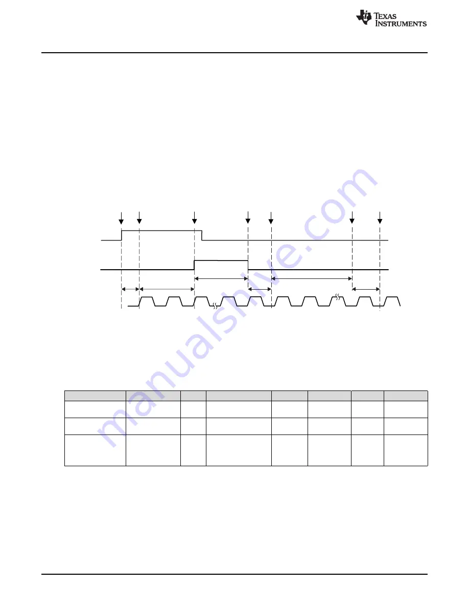
Start
Sampling
Stop
Sampling
Conversion
Complete
SAMPCON
SHI
t
sample
t
convert
t
phase
16 × ADC14CLK
Start
Conversion
ADC14CLK
t
clk
Clock
Request
Data
Stored
t
dmove
Note: If internal ADC reference buffers are used, the SHI signal is gated while ADC14RDYIFG = 0.
Clock
Available
t
sync
Precision ADC Operation
848
SLAU356I – March 2015 – Revised June 2019
Copyright © 2015–2019, Texas Instruments Incorporated
Precision ADC
22.2.6.2 Pulse Sample Mode
The pulse sample mode is selected when ADC14SHP = 1. The SHI signal is used to trigger the sampling
timer. The ADC14SHT0x and ADC14SHT1x bits in ADC14CTL0 control the interval of the sampling timer
that defines the SAMPCON sample period t
sample.
The sampling timer asserts SAMPCON signal when the
reference and internal buffer is settled if the internal reference is used. It takes t
sync
for synchronization
with ADC14CLK before asserting SAMPCON signal. see
and
for total sample and
conversion cycles in pulse sample mode.
There is an autoscan measurement mode (see
) which repeats measurements
automatically. In this mode, the t
clk
and t
sync
are only applicable to the first measurement. In subsequent
measurements these cycles are not applicable.
The ADC14SHTx bits select the sampling time in 4x multiples of ADC14CLK. The programmable range of
sampling timer is 4 to 192 ADC14CLK cycles. ADC14SHT0x selects the sampling time for ADC14MCTL8
to ADC14MCTL23, and ADC14SHT1x selects the sampling time for ADC14MCTL0 to ADC14MCTL7 and
ADC14MCTL24 to ADC14MCTL31.
Figure 22-4. Pulse Sample Mode in 14-Bit Mode
summarizes the sample and conversion time for pulse sample mode and extended sample
mode.
(1)
The time for reference settling is not included
(2)
Up to 3 cycles when SHI is generated based on the same clock source of the Precision ADC or 5 cycles when a different clock
source is used to generate SHI signal
(3)
Successive conversions
Table 22-1. Sample & Conversion Time
(1)
Mode
t
clk
t
sync
t
sample
t
phase
t
convert
t
dmove
Total
Pulse Sample Mode
with ADC14MSC = 0
Up to 3 or 5
cycles
(2)
2
cycles
Minimum 4 cycles
1 cycle
16 cycles for
14-bit
1 cycle
27 or 29
cycles
Pulse Sample Mode
with ADC14MSC = 1
N/A
(3)
N/A
(3)
Minimum 4 cycles
1 cycle
16 cycles for
14-bit
1 cycle
22 cycles
Extended Sample
Mode
N/A
N/A
See the device
datasheet for
minimum sample
period
1 cycle
16 cycles for
14-bit
1 cycle
18 + sampling
cycles
22.2.6.3 Sample Timing Considerations
When SAMPCON = 0, all A
x
inputs are high impedance. When SAMPCON = 1, the selected A
x
input can
be modeled as an RC low-pass filter during the sampling time t
sample
(see
). An internal MUX-on
input resistance R
I
(see device-specific data sheet) in series with capacitor C
I
(see device-specific data
sheet) is seen by the source. The capacitor C
I
voltage V
C
must be charged to within one-half LSB of the
source voltage V
S
for an accurate n-bit conversion, where n is the bits of resolution required.


