50
External I/O Circuits
Section 3-3
(3) When selecting a sensor for the origin proximity input signal (origin return
deceleration LS), use a sensor such as a Photoelectric Sensor, which
does not have chattering, because the origin signal is detected after the
input goes from ON to OFF during the origin search. If a switch with con-
tacts is used, the origin position may shift due to the switch contact's chat-
tering.
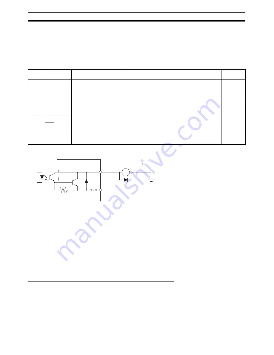
CN1 Control Output Signals
Control Output Circuit
Note
The circuit is equipped with an auto-resetting circuit breaker to protect the out-
put. Even if an overcurrent trips the breaker, the breaker will reset automati-
cally after a certain time elapses with no current. (Ver. 37 and later Servo
Drives are equipped with the auto-resetting circuit breakers.)
3-3-5
W-series Servo Drive I/O Signals (R88D-WN
@
-ML2 with
MECHATROLINK-II Built-in Communications)
This section explains the I/O signals used between the PCU and a W-series
Servo Drive equipped with built-in MECHATROLINK-II communications.
Use the
OMNUC W Series User's Manual
(Cat. No. I544) together with this
manual for information on I/O signals.
Terminal Arrangement of the Control I/O Connector (CN1)
When using W-series Servo Drives equipped with built-in MECHATROLINK-II
communications, the default control I/O signal allocations are the standard
Servo Drive settings for using MECHATROLINK.
The following diagram shows the terminal arrangement of the W-series Servo
Drive's Control I/O Connector (CN1) when MECHATROLINK is being used
with the Servo Drive's default settings.
This diagram shows only the I/O signals used when connecting to the PCU.
Pin no.
Signal
Name
Function/Interface
Control
mode
25
INP1
Positioning completed
output 1
The position deviation is less than positioning comple-
tion range 1 (Pn500). (This signal is always OFF in con-
trol modes other than position control mode.)
Position
26
INP1COM
27
BKIR
Brake interlock output
This is the holding brake timing signal that is output
according to the settings in parameters Pn506, Pn507,
and Pn508.
All modes
28
BKIRCOM
29
READY
Servo ready output
Turned ON if there are no errors after the control and
main circuit power supplies are turned ON.
All modes
30
READYCOM
31
ALM
Alarm output
This output turns OFF when there is a Servo Drive
alarm.
All modes
32
ALMCOM
Shell
FG
Frame ground
Use this terminal to connect the cable's shield and FG
wire.
All modes
Servo Drive
To other output circuit
X
Di
+
−
See note.
Di: Diode providing surge-voltage protection (Use a high-speed diode.)
External power
supply
24
±
1 VDC
Voltage: 30 VDC max.
Output current: 50 mA max.
Summary of Contents for CJ1W-NC271 - 12-2009
Page 2: ......
Page 4: ...iv ...
Page 6: ...vi ...
Page 22: ...xxii ...
Page 58: ...30 Starting Operation Section 2 2 ...
Page 244: ...216 Axis Operating Input Memory Areas Section 4 8 ...
Page 264: ...236 Transferring Servo Parameters Section 5 3 ...
Page 396: ...368 Linear Interpolation Section 9 7 ...
Page 648: ...620 List of Error Codes Appendix D ...
Page 674: ...646 Additional Functions for the CJ1W NCF71 MA Appendix F ...
Page 684: ...656 Index ...
Page 686: ...658 Revision History ...


