518
Performance Characteristics
Appendix A
Effect on CPU Unit Cycle Time
When a single PCU is mounted, the CPU Unit's cycle time increases with the amount of Servo Drive axes con-
nected to the PCU, as follows:
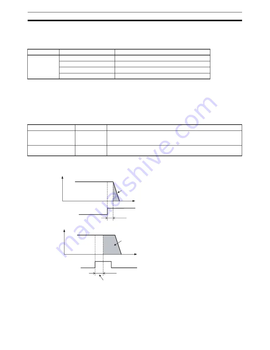
External Input Response Time
The response time is as shown below for external input signals, such as limit inputs and interrupt inputs. The
following response times indicate the time until the Servo Drive starts operating according to the function corre-
sponding to the input signal.
The command response time is required for the status of the signal that was input to be reflected in the input
area of the CPU Unit.
Note
The numerical values are obtained when a W-series Servo Drive is used with a FNY-NS115 MECHA-
TROLINK-II I/F Unit.
Difference in Start Times for Simultaneously Started Axes
There is no difference in start times between axes when multiple axes are started at the same time (the bit to
start operation turns ON at the same I/O refresh timing).
Model
Number of axes connected
Additional time for each PCU connected
CJ1W-NCF71
1
0.2 ms
3
0.3 ms
6
0.4 ms
16
1.0 ms
External input signal
Response time
Details
Limit input signal
2 ms max.
Response time until the Servo Drive starts the Servomotor's stop operation
according to the setting in Servo Parameter Pn001.1 in response to input of
the limit input signal.
Interrupt input signal
3 ms max.
Response time until the interrupt feeding operation starts after input of the
interrupt input signal for interrupt feeding.
Time
1
0
Time
Interrupt input response time
1
0
Travel direction limit input
Speed
Speed
Interrupt input signal
(external latch input)
After the Servo Drive detects that the limit input
signal has turned ON and until it stops axis
operation (area shaded in gray), the axis will
operate according to the
Select Stop when
Prohibited Drive Is Input
(Pn001.1) setting in the
Servo Parameters.
Limit input response time
Interrupt feeding amount
(Final travel distance for external positioning:
Servo Parameter Pn814)
In interrupt feeding, this indicates the response time from
after the Servo Drive detects that the interrupt input
signal is ON until interrupt feeding positioning starts.
Summary of Contents for CJ1W-NC271 - 12-2009
Page 2: ......
Page 4: ...iv ...
Page 6: ...vi ...
Page 22: ...xxii ...
Page 58: ...30 Starting Operation Section 2 2 ...
Page 244: ...216 Axis Operating Input Memory Areas Section 4 8 ...
Page 264: ...236 Transferring Servo Parameters Section 5 3 ...
Page 396: ...368 Linear Interpolation Section 9 7 ...
Page 648: ...620 List of Error Codes Appendix D ...
Page 674: ...646 Additional Functions for the CJ1W NCF71 MA Appendix F ...
Page 684: ...656 Index ...
Page 686: ...658 Revision History ...


