354
Torque Limit Function
Section 9-6
In interrupt feeding as well as normal direct operations, the target position
(target position for when no interrupt input signal is input), target speed, and
override value can be changed by executing another movement command.
Note that, however, in the interval of positioning for the final travel distance for
external positioning after the input of the interrupt input signal, another
INTERRUPT FEEDING cannot be executed (it will be ignored).
9-5-5
Present Position during Interrupt Feeding
The positioning range for direct operation (ABSOLUTE MOVEMENT and
RELATIVE MOVEMENT) is a command present position range of
−
2,147,483,648 to 2,147,483,647 (command units) when it is not limited by
limit input signals or software limits. (For details on the command present
position, refer to
7-3 Coordinate System and Present Position
. For details on
RELATIVE MOVEMENT, refer to
Executing RELATIVE MOVEMENT
in
9-4-1
Starting Direct Operation
.)
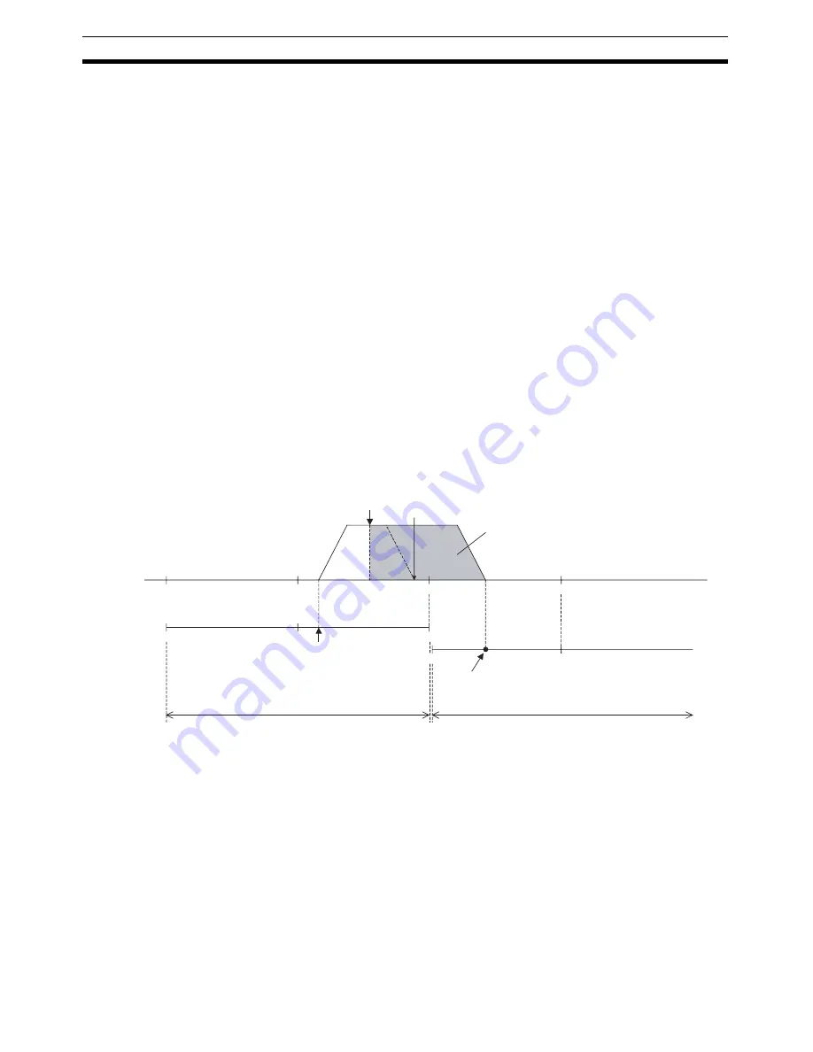
When INTERRUPT FEEDING is executed, the positioning range and position
command value setting range are the same, but the positioning range is sub-
ject to the following conditions when interrupt input signals are input near the
upper limit/lower limit of the positioning range.
When the interrupt feeding operation after interrupt input exceeds the upper
or lower limit of the positioning range due to the
Final Travel Distance for
External Positioning
setting and the input position of the interrupt input signal,
the current position reference point (i.e., the origin) and the positioning range
change and positioning to the original position is no longer possible.
When interrupt feeding is used, set the limit inputs, software limits, and other
required settings, and make sure that the positioning range is not exceeded
due to the interrupt feeding operation.
9-6
Torque Limit Function
When using a W-series Servo Drive, set Servo Parameters
Forward Rotation
External Current Limit
(Pn404) and
Reverse Rotation External Current Limit
(Pn405), and turn ON the Forward Rotation External Current Limit Designa-
tion Bit and Reverse Rotation External Current Limit Designation Bit in the
Axis Operating Output Memory Area when starting a direct operation to apply
a current (torque) limit during direct operation.
0
P
0
0
−
2,147,483,648
−
2,147,483,648
2,147,483,647
2,147,483,647
−
2,147,483,648
4,294,967,296
2,147,483,647
Physical position
PCU present position
Positioning range when interrupt feeding is started
Interrupt feeding start
Interrupt input signal
Positioning without input of
internal input signal
Final travel distance for external positioning
Position after interrupt feeding
Positioning range from point P
Summary of Contents for CJ1W-NC271 - 12-2009
Page 2: ......
Page 4: ...iv ...
Page 6: ...vi ...
Page 22: ...xxii ...
Page 58: ...30 Starting Operation Section 2 2 ...
Page 244: ...216 Axis Operating Input Memory Areas Section 4 8 ...
Page 264: ...236 Transferring Servo Parameters Section 5 3 ...
Page 396: ...368 Linear Interpolation Section 9 7 ...
Page 648: ...620 List of Error Codes Appendix D ...
Page 674: ...646 Additional Functions for the CJ1W NCF71 MA Appendix F ...
Page 684: ...656 Index ...
Page 686: ...658 Revision History ...


