


Appendix A: Specifications
724
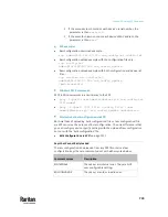
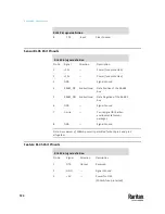
RJ-45 Pin/signal definition
8
CTS
Input
Clear to send
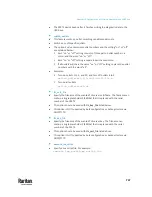
Sensor RJ-45 Port Pinouts
RJ-45 Pin/signal definition
Pin No. Signal
Direction
Description
1
+12V
―
Power (fuse protected)
2
+12V
―
Power (fuse protected)
3
GND
―
Signal Ground
4
RS485_DP
bi-directional
Data Positive of the RS-485
bus
5
RS485_DN bi-directional
Data Negative of the RS-485
bus
6
GND
―
Signal Ground
7
1-wire
―
1-wire signal for Raritan
environmental sensor
packages
8
GND
―
Signal Ground
Note: A maximum of 500mA power is permitted for both pin 1 and pin 2
altogether.
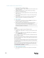
Feature RJ-45 Port Pinouts
RJ-45 Pin/signal definition
Pin No.
Signal
Direction
Description
1
DTR
Output
Reserved
2
GND
―
Signal Ground
3
+5V
―
Power for CIM
(200mA, fuse protected)
Summary of Contents for Raritan PX3TS
Page 4: ......
Page 6: ......
Page 20: ......
Page 80: ...Chapter 4 Connecting External Equipment Optional 60...
Page 109: ...Chapter 5 PDU Linking 89...
Page 117: ...Chapter 5 PDU Linking 97...
Page 441: ...Chapter 7 Using the Web Interface 421...
Page 464: ...Chapter 7 Using the Web Interface 444...
Page 465: ...Chapter 7 Using the Web Interface 445 Continued...
Page 746: ...Appendix A Specifications 726...
Page 823: ...Appendix I RADIUS Configuration Illustration 803 Note If your PX3TS uses PAP then select PAP...
Page 828: ...Appendix I RADIUS Configuration Illustration 808 14 The new attribute is added Click OK...
Page 829: ...Appendix I RADIUS Configuration Illustration 809 15 Click Next to continue...
Page 860: ...Appendix J Additional PX3TS Information 840...
Page 890: ...Appendix K Integration 870 3 Click OK...
Page 900: ......


