Section 2: General operation
Model 2281S-20-6 DC Power Supply and Battery Simulator Reference Manual
2-16
077114601 / March 2019
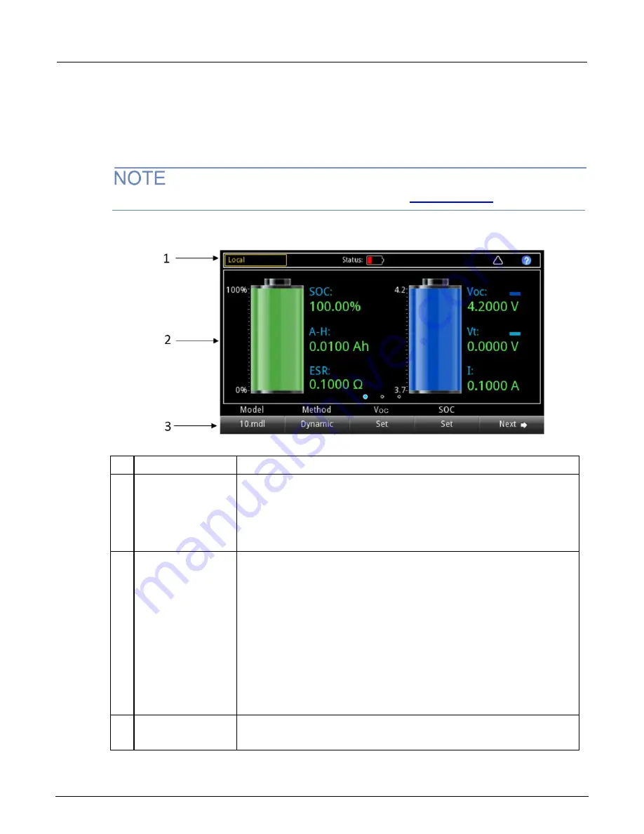
Home screen for the battery simulator function
The following default screen is displayed when you choose the battery simulation function.
Descriptions of the numbered screen areas are in the table following the figure.
For details about how to use the battery simulator function, see
(on page 3-69).
Figure 18: Battery simulation home screen 1
#
Screen element
Description
1
System status and
event indicators
These indicators provide information about the present state of the instrument. Some
of the indicators open a dialog box with more information or a settings menu when
selected.
When the
Status
icon is partially filled with red, it indicates that the battery is being
discharged.
When the
Status
icon is filled with a lightning bolt symbol, it indicates that the battery
is being charged.
2
OUTPUT view area
This part of the screen displays the status of the battery simulation.
The battery symbol on the left represents the remaining battery capacity.
SOC
means state of charge, the remaining battery capacity shown as a
percentage.
A-H
indicates the battery capacity in ampere-hours.
ESR
indicates the equivalent battery resistance.
The battery symbol in the right represents the output voltage.
Voc
is the open-circuit voltage, represented in dark blue.
Vt
is the battery voltage when it is connected to a load. It changes depending
on the load. It is represented in light blue.
I
displays the charging/discharging current. When the value is in negative (
–),
the battery is being charged.
3
Soft-key area
Shows the present setting values. You can change these values by pressing the key
below the screen.
By pressing the
Next
button, you can access additional screens with more soft keys.


