Part 3: Review on Replacement of MR-J2S-_B_ with MR-J4-_B_
3 - 12
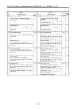
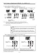
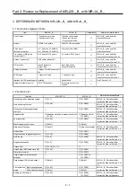
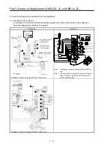
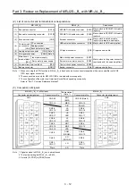
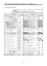
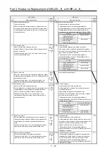
(2) List of connector and terminal block correspondence
MR-J2S-_B_
→
MR-J4-_B_ Precautions
(1) Bus cable connector
[CN1A]
SSCNET III/H cable connector [CN1A]
Must switch to SSCNET III/H cable
(option).
(2) Bus cable-connecting connector
[CN1B]
SSCNET III/H cable connector [CN1B]
Must switch to SSCNET III/H cable
(option).
(3) Encoder
connector
[CN2] Encoder
connector
[CN2]
Must switch to encoder cable
(option) or prepare a new cable.
(4)
Communicati
on connector
[CN3]
PC connection
USB communication connector [CN5] Must switch to USB cable (option).
Analog monitor
I/O signal connector
[CN3] Prepare a new cable.
Encoder output pulses
(8) Analog output connector
[CN4] (Note 2)
(9) I/O signal connector
[CON2] (Note 2)
(5)
Main circuit
terminal block
[TE1]
Input power supply
Main circuit power connector
[CNP1]
Must switch to the power connector
(enclosed with the servo amplifier).
Servo motor power supply
Servo motor power connector [CNP3]
(6) Control circuit terminal block
[TE2]
Control circuit power connector [CNP2]
(7) Battery connector
[CON1]
Battery connector
[CN4] Prepare a new battery.
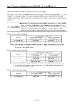
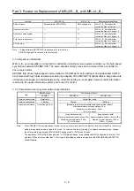
Note 1. When not using the STO function in MR-J4-_B_, attach a short-circuit connector supplied with a servo amplifier onto CN8
(STO input signal connector).
2. These connectors are only for MR-J2S-11KB or models with more capacity.
3. The configuration of the main circuit terminal block differs depending on capacity.
Refer to "Part 7: Common Reference Material".
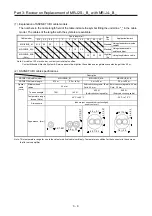
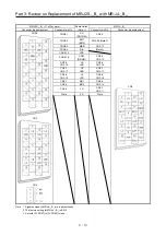
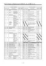
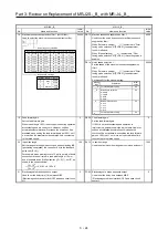
(3) Comparison of signals
MR-J2S-_B_ <7 kW or less>
Abbreviation
(Note 1)
MR-J4-_B_
Connector pin assignment
Connector pin No.
Connector pin No.
Connector pin assignment
CN3
CN3-20
EM1
(EM2)
CN3-20 (Note 2)
CN3
CN3-13 MBR CN3-13
DB
(Note
3)
CN3-6
CN3-16
LA
LAR
CN3-6
CN3-16
CN3-7
CN3-17
LB
LBR
CN3-7
CN3-17
CN3-8
CN3-18
LZ
LZR
CN3-8
CN3-18
CN3-4 MO1 CN3-4
CN3-14 MO2 CN3-14
CN3-10 VDD
CN3-5
COM
(DICOM)
CN3-5
CN3-10
CN3-3
SG
(DOCOM)
CN3-3
CN3-1
CN3-11
LG
CN3-1
CN3-11
Plate SD Plate
Note 1. Signals unique to MR-J4-_B_ are in parentheses.
2. The factory setting for MR-J4-_B_ is EM2.
3. Set with [Pr. PD07] to [PD09] for use.
Содержание MELSERVO-J2-Super Series
Страница 18: ...Part 1 Summary of MR J2S MR J2M Replacement 1 1 Part 1 Summary of MR J2S MR J2M Replacement ...
Страница 31: ...Part 1 Summary of MR J2S MR J2M Replacement 1 14 MEMO ...
Страница 109: ...Part 3 Review on Replacement of MR J2S _B_ with MR J4 _B_ 3 32 MEMO ...
Страница 161: ...Part 4 Review on Replacement of MR J2S _CP_ CL_ with MR J4 _A_ RJ 4 52 MEMO ...
Страница 219: ...Part 5 Review on Replacement of MR J2S 30 kW or Higher Capacity Models with MR J4 DU_ 5 58 MEMO ...
Страница 220: ...Part 6 Review on Replacement of MR J2M with MR J4 6 1 Part 6 Review on Replacement of MR J2M with MR J4 ...
Страница 239: ...Part 6 Review on Replacement of MR J2M with MR J4 6 20 MEMO ...
Страница 240: ...Part 7 Common Reference Material 7 1 Part 7 Common Reference Material ...
Страница 284: ...Part 7 Common Reference Material 7 45 Click Update Project ...
Страница 342: ...Part 8 Review on Replacement of Motor 8 1 Part 8 Review on Replacement of Motor ...
Страница 409: ...Part 8 Review on Replacement of Motor 8 68 MEMO ...
Страница 461: ...Part 9 Review on Replacement of Optional Peripheral Equipment 9 52 MEMO ...
Страница 462: ...Part 10 Startup Procedure Manual 10 1 Part 10 Startup Procedure Manual ...
Страница 464: ... Appendix 1 Summary of MR J4_B_ RJ020 MR J4 T20 Appendix 1 1 Appendix 1 Summary of MR J4_B_ RJ020 MR J4 T20 ...

