


A - 4
(2) Wiring
CAUTION
Wire the equipment correctly and securely. Otherwise, the servo motor may operate unexpectedly.
Do not install a power capacitor, surge killer, or radio noise filter (optional FR-BIF) on the output side of
the servo amplifier.
Because installation of these items may cause the servo motor to malfunction, connect the wires to the
correct phase terminals (U/V/W) of the servo amplifier and servo motor power supply.
Directly connect the servo amplifier power output (U/V/W) to the servo motor power input (U/V/W). Do not
let a magnetic contactor, etc. intervene. Otherwise, it may cause a malfunction.
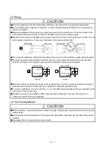
The connection diagrams in this Instruction Manual are shown for sink interfaces, unless stated otherwise.
The surge absorbing diode installed to the DC relay for control output should be fitted in the specified
direction. Otherwise, the emergency stop and other protective circuits may not operate.
When the cable is not tightened enough to the terminal block, the cable or terminal block may generate
heat because of the poor contact. Be sure to tighten the cable with specified torque.
To avoid a malfunction, do not connect the U, V, W, and CN2 phase terminals of the servo amplifier to the
servo motor of an incorrect axis.
Configure a circuit to turn off EM2 or EM1 when the main circuit power is turned off to prevent an
unexpected restart of the servo amplifier.
(3) Trial run/adjustment
CAUTION
Before operation, check the parameter settings. Improper settings may cause some machines to operate
unexpectedly.
Never perform extreme adjustment or changes to the parameters; otherwise, the operation may become
unstable.
Keep away from moving parts in a servo-on state.
RA
RA
Servo amplifier
Servo amplifier
DOCOM
Control output
signal
DOCOM
Control output
signal
24 V DC
24 V DC
For sink output
interface
For source output
interface
U
M
V
W
U
V
W
U
M
V
W
U
V
W
Servo amplifier
Servo motor
Servo amplifier
Servo motor
Содержание MELSERVO-J2-Super Series
Страница 18: ...Part 1 Summary of MR J2S MR J2M Replacement 1 1 Part 1 Summary of MR J2S MR J2M Replacement ...
Страница 31: ...Part 1 Summary of MR J2S MR J2M Replacement 1 14 MEMO ...
Страница 109: ...Part 3 Review on Replacement of MR J2S _B_ with MR J4 _B_ 3 32 MEMO ...
Страница 161: ...Part 4 Review on Replacement of MR J2S _CP_ CL_ with MR J4 _A_ RJ 4 52 MEMO ...
Страница 219: ...Part 5 Review on Replacement of MR J2S 30 kW or Higher Capacity Models with MR J4 DU_ 5 58 MEMO ...
Страница 220: ...Part 6 Review on Replacement of MR J2M with MR J4 6 1 Part 6 Review on Replacement of MR J2M with MR J4 ...
Страница 239: ...Part 6 Review on Replacement of MR J2M with MR J4 6 20 MEMO ...
Страница 240: ...Part 7 Common Reference Material 7 1 Part 7 Common Reference Material ...
Страница 284: ...Part 7 Common Reference Material 7 45 Click Update Project ...
Страница 342: ...Part 8 Review on Replacement of Motor 8 1 Part 8 Review on Replacement of Motor ...
Страница 409: ...Part 8 Review on Replacement of Motor 8 68 MEMO ...
Страница 461: ...Part 9 Review on Replacement of Optional Peripheral Equipment 9 52 MEMO ...
Страница 462: ...Part 10 Startup Procedure Manual 10 1 Part 10 Startup Procedure Manual ...
Страница 464: ... Appendix 1 Summary of MR J4_B_ RJ020 MR J4 T20 Appendix 1 1 Appendix 1 Summary of MR J4_B_ RJ020 MR J4 T20 ...