Part 9: Review on Replacement of Optional Peripheral Equipment
9 - 21
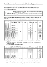
4.3.2 MR-J4 series, molded-case circuit breakers, fuses, and magnetic contactors (recommended)
(1) For main circuit power supply
CAUTION
Select a molded-case circuit breaker with a short shut-off time to prevent smoking
and fire from the servo amplifier.
Always use one molded-case circuit breaker and one magnetic contactor with one
servo amplifier.
When using a fuse instead of the molded-case circuit breaker, use the one having the specifications given in
this section.
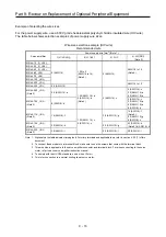
Molded-case circuit breakers, fuses, and magnetic contactors
Servo amplifier
Molded-case circuit breaker (Note 1)
Fuse
Magnetic
contactor
(Note 2)
Frame, rated current
Voltage AC [V]
Class
Current [A]
Voltage AC [V]
MR-J4-10_(-RJ)
30 A frame 5 A
240 T
10
300
S-N10
S-T10
MR-J4-20_(-RJ)
MR-J4-40_(-RJ)
30 A frame 10 A
15
MR-J4-60_(-RJ)
30 A frame 15 A
20
MR-J4-70_(-RJ)
MR-J4-100_(-RJ)
MR-J4-200_(-RJ)
30 A frame 20 A
40
S-N20 (Note 3)
S-T21
MR-J4-350_(-RJ)
30 A frame 30 A
70
S-N20
S-T21
MR-J4-500_(-RJ)
50 A frame 50 A
125
S-N35
MR-J4-700_(-RJ)
100 A frame 75 A
150
S-N50
MR-J4-11K_(-RJ)
100 A frame 100 A
200
MR-J4-15K_(-RJ)
125 A frame 125 A
250
S-N65
MR-J4-22K_(-RJ)
225 A frame 175 A
350
S-N95
MR-J4-10_1(-RJ)
30 A frame 5 A
10
S-N10
S-T10
MR-J4-20_1(-RJ)
30 A frame 10 A
15
MR-J4-40_1(-RJ)
30 A frame 15 A
20
Note 1. In order for the servo amplifier to comply with the UL/CSA standard, refer to the applicable "Servo Amplifier Instruction
Manual".
2. Use a magnetic contactor with an operation delay time (interval between current being applied to the coil until closure of
contacts) of 80 ms or less.
3. S-N18 can be used when auxiliary contact is not required.
Servo amplifier
Molded-case circuit breaker (Note 1, 3)
Fuses
Magnetic
contactor
(Note 2)
Frame, rated current
Voltage AC [V]
Class
Current [A]
Voltage AC [V]
MR-J4-60_4(-RJ)
30 A frame 5 A
480 T
10
600
S-N10
S-T10
MR-J4-100_4(-RJ)
30 A frame 10 A
15
MR-J4-200_4(-RJ)
30 A frame 15 A
25
MR-J4-350_4(-RJ)
30 A frame 20 A
35
S-N18
S-T21
MR-J4-500_4(-RJ)
30 A frame 20 A
50
MR-J4-700_4(-RJ)
30 A frame 30 A
65
S-N20
S-T21
MR-J4-11K_4(-RJ) 50 A frame 50 A
100
S-N25
MR-J4-15K_4(-RJ) 60 A frame 60 A
150
S-N35
MR-J4-22K_4(-RJ) 100 A frame 100 A
175
S-N50
Note 1. In order for the servo amplifier to comply with the UL/CSA standard, refer to the applicable "Servo Amplifier Instruction
Manual".
2. Use a magnetic contactor with an operation delay time (interval between current being applied to the coil until closure of
contacts) of 80 ms or less.
3. Use a molded-case circuit breaker with operating characteristics equivalent or higher than our multi-purpose product.
Содержание MELSERVO-J2-Super Series
Страница 18: ...Part 1 Summary of MR J2S MR J2M Replacement 1 1 Part 1 Summary of MR J2S MR J2M Replacement ...
Страница 31: ...Part 1 Summary of MR J2S MR J2M Replacement 1 14 MEMO ...
Страница 109: ...Part 3 Review on Replacement of MR J2S _B_ with MR J4 _B_ 3 32 MEMO ...
Страница 161: ...Part 4 Review on Replacement of MR J2S _CP_ CL_ with MR J4 _A_ RJ 4 52 MEMO ...
Страница 219: ...Part 5 Review on Replacement of MR J2S 30 kW or Higher Capacity Models with MR J4 DU_ 5 58 MEMO ...
Страница 220: ...Part 6 Review on Replacement of MR J2M with MR J4 6 1 Part 6 Review on Replacement of MR J2M with MR J4 ...
Страница 239: ...Part 6 Review on Replacement of MR J2M with MR J4 6 20 MEMO ...
Страница 240: ...Part 7 Common Reference Material 7 1 Part 7 Common Reference Material ...
Страница 284: ...Part 7 Common Reference Material 7 45 Click Update Project ...
Страница 342: ...Part 8 Review on Replacement of Motor 8 1 Part 8 Review on Replacement of Motor ...
Страница 409: ...Part 8 Review on Replacement of Motor 8 68 MEMO ...
Страница 461: ...Part 9 Review on Replacement of Optional Peripheral Equipment 9 52 MEMO ...
Страница 462: ...Part 10 Startup Procedure Manual 10 1 Part 10 Startup Procedure Manual ...
Страница 464: ... Appendix 1 Summary of MR J4_B_ RJ020 MR J4 T20 Appendix 1 1 Appendix 1 Summary of MR J4_B_ RJ020 MR J4 T20 ...

