background image

Part 8: Review on Replacement of Motor 


8 -  30 


Series 

Target product 

Replacement product 

Model 

Moment of  

inertia J 

× 10

-4

 kg•m

2


Load inertia 

moment ratio 

Model 

Moment of  

inertia J 

× 10

-4

 kg•m

2


Load inertia 

moment ratio  

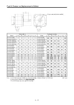
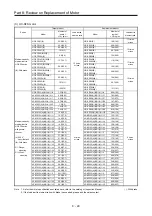
Medium capacity, 
medium inertia 
HC-SFS series 
with general 
reducer 
 
(4): 400 V 

specifications 

(B): With brake 
 
G1: Flange-

mounting 

G1H: Foot-

mounting 

HC-SFS352(4)(B)G1(H) 1/43 

106.5(116.5) 

4 times  

or less 

HG-SR352(4)(B)G1(H) 1/43 

105(114) 

4 times  

or less 

HC-SFS352(4)(B)G1(H) 1/59 

105.9(115.9) 

HG-SR352(4)(B)G1(H) 1/59 

104(113) 

HC-SFS502(4)(B)G1(H) 1/11 

113.4(123.4) 

HG-SR502(4)(B)G1(H) 1/11 

114(123) 

HC-SFS502(4)(B)G1(H) 1/17 

109.4(119.4) 

HG-SR502(4)(B)G1(H) 1/17 

110(119) 

HC-SFS502(4)(B)G1(H) 1/29 

138.5(148.5) 

HG-SR502(4)(B)G1(H) 1/29 

141(150) 

HC-SFS502(4)(B)G1(H) 1/35 

138.0(148.0) 

HG-SR502(4)(B)G1(H) 1/35 

140(150) 

HC-SFS502(4)(B)G1(H) 1/43 

137.0(147.0) 

HG-SR502(4)(B)G1(H) 1/43 

139(149) 

HC-SFS702(4)(B)G1(H) 1/11 

198.8(208.8) 

HG-SR702(4)(B)G1(H) 1/11 

190(199) 

HC-SFS702(4)(B)G1(H) 1/17 

190.0(200.0) 

HG-SR702(4)(B)G1(H) 1/17 

182(192) 

HC-SFS702(4)(B)G1(H) 1/29 

197.5(207.5) 

HG-SR702(4)(B)G1(H) 1/29 

192(202) 

HC-SFS702(4)(B)G1(H) 1/35 

197.0(207.0) 

HG-SR702(4)(B)G1(H) 1/35 

192(201) 

HC-SFS702(4)(B)G1(H) 1/43 

256.8(266.8) 

HG-SR702(4)(B)G1(H) 1/43 

267(277) 

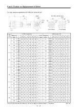
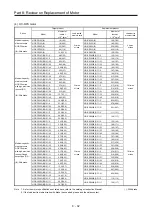
Medium capacity, 
medium inertia 
HC-SFS series 
with high precision 
reducer (G2) 
 
(4): 400 V 

specifications 

(B): With brake 

HC-SFS52(4)(B)G2 1/5 

7.9(9.6) 

5 times  

or less 

HG-SR52(4)(B)G7 1/5 

7.95(10.2) 

10 times  

or less 

HC-SFS52(4)(B)G2 1/9 

7.55(9.25) 

HG-SR52(4)(B)G7 1/11 

7.82(10.0) 

HC-SFS52(4)(B)G2 1/20 

8.03(9.73) 

HG-SR52(4)(B)G7 1/21 

10.2(12.4) 

HC-SFS52(4)(B)G2 1/29 

9.4(11.1) 

HG-SR52(4)(B)G7 1/33 

9.96(12.2) 

HC-SFS52(4)(B)G2 1/45 

8.43(10.1) 

HG-SR52(4)(B)G7 1/45 

9.96(12.2) 

HC-SFS102(4)(B)G2 1/5 

15.0(16.7) 

HG-SR102(4)(B)G7 1/5 

12.3(14.5) 

HC-SFS102(4)(B)G2 1/9 

14.6(16.3) 

HG-SR102(4)(B)G7 1/11 

15.0(17.2) 

HC-SFS102(4)(B)G2 1/20 

18.4(20.1) 

HG-SR102(4)(B)G7 1/21 

14.5(16.7) 

HC-SFS102(4)(B)G2 1/29 

16.5(18.2) 

HG-SR102(4)(B)G7 1/33 

16.3(18.5) 

HC-SFS102(4)(B)G2 1/45 

20.3(22.0) 

HG-SR102(4)(B)G7 1/45 

16.3(18.5) 

HC-SFS152(4)(B)G2 1/5 

21.2(22.9) 

HG-SR152(4)(B)G7 1/5 

16.7(18.9) 

HC-SFS152(4)(B)G2 1/9 

24.7(26.4) 

HG-SR152(4)(B)G7 1/11 

19.4(21.6) 

HC-SFS152(4)(B)G2 1/20 

24.6(26.3) 

HG-SR152(4)(B)G7 1/21 

21.7(23.9) 

HC-SFS152(4)(B)G2 1/29 

30.3(32.0) 

HG-SR152(4)(B)G7 1/33 

20.7(22.9) 

HC-SFS152(4)(B)G2 1/45 

26.5(28.2) 

HG-SR152(4)(B)G7 1/45 

20.7(22.9) 

HC-SFS202(4)(B)G2 1/5 

49.6(59.6) 

HG-SR202(4)(B)G7 1/5 

51.7(61.4) 

HC-SFS202(4)(B)G2 1/9 

47.2(57.2) 

HG-SR202(4)(B)G7 1/11 

51.3(61.0) 

HC-SFS202(4)(B)G2 1/20 

59.6(69.6) 

HG-SR202(4)(B)G7 1/21 

53.3(63.0) 

HC-SFS202(4)(B)G2 1/29 

52.8(62.8) 

HG-SR202(4)(B)G7 1/33 

52.2(61.9) 

HC-SFS202(4)(B)G2 1/45 

49.1(59.1) 

HG-SR202(4)(B)G7 1/45 

52.2(61.9) 

HC-SFS352(4)(B)G2 1/5 

99.4(109.4) 

HG-SR352(4)(B)G7 1/5 

83.5(93.1) 

HC-SFS352(4)(B)G2 1/9 

91.5(101.5) 

HG-SR352(4)(B)G7 1/11 

87.0(96.6) 

HC-SFS352(4)(B)G2 1/20 

99.1(109.1) 

HG-SR352(4)(B)G7 1/21 

85.1(94.7) 

HC-SFS502(4)(B)G2 1/5 

118.4(128.4) 

HG-SR502(4)(B)G7 1/5 

111(121) 

HC-SFS502(4)(B)G2 1/9 

110.5(120.5) 

HG-SR502(4)(B)G7 1/11 

108(117) 

HC-SFS702(4)(B)G2 1/5 

177.4(187.4) 

HG-SR702(4)(B)G7 1/5 

163(173)  


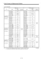
Note   1. 


2. 

As for the motor specifications not listed here, refer to the catalog or Instruction Manual.  
If the load inertia moment ratio with brake is exceeded, please ask the sales contact. 

(  ): With brake


Содержание MELSERVO-J2-Super Series

Страница 1: ... 8 BC Aeroplaza office 607 196210 St Petersburg Russia Tel 7 812 449 51 34 Sweden Mitsubishi Electric Europe B V Scandinavia Hedvig Mollersgata 6 223 55 Lund Sweden Tel 46 8 625 10 00 Turkey Mitsubishi Electric Turkey A S Umraniye Branch Serifali Mah Kale Sok No 41 34775 Umraniye Istanbul Turkey Tel 90 216 969 2500 UAE Mitsubishi Electric Europe B V Dubai Branch Dubai Silicon Oasis P O BOX 341241 ...

Страница 2: ...injury CAUTION Indicates that incorrect handling may cause hazardous conditions resulting in medium or slight injury to personnel or may cause physical damage Note that the CAUTION level may lead to a serious consequence according to conditions Please follow the instructions of both levels because they are important to personnel safety What must not be done and what must be done are indicated by t...

Страница 3: ...c shock To prevent electric shock always connect the protective earth PE terminal marked of the servo amplifier to the protective earth PE of the cabinet To avoid an electric shock insulate the connections of the power supply terminals 2 To prevent fire note the following CAUTION Install the servo amplifier servo motor and regenerative resistor on incombustible material Installing them directly or...

Страница 4: ... inner surface of the cabinet or other devices Do not install or operate the servo amplifier and servo motor which have been damaged or have any parts missing Do not block the intake and exhaust areas of the servo amplifier Otherwise it may cause a malfunction Do not drop or strike the servo amplifier and servo motor Isolate them from all impact loads When you keep or use the equipment please fulf...

Страница 5: ...nd other protective circuits may not operate When the cable is not tightened enough to the terminal block the cable or terminal block may generate heat because of the poor contact Be sure to tighten the cable with specified torque To avoid a malfunction do not connect the U V W and CN2 phase terminals of the servo amplifier to the servo motor of an incorrect axis Configure a circuit to turn off EM...

Страница 6: ...fe and mechanical structure e g where a ball screw and the servo motor are coupled via a timing belt the electromagnetic brake may not hold the motor shaft To ensure safety install a stopper on the machine side 5 Corrective actions CAUTION Ensure safety by confirming the power off etc before performing corrective actions Otherwise it may cause an accident When it is assumed that a hazardous condit...

Страница 7: ... every 10 years when it is used in general environment When using a servo amplifier whose power has not been turned on for a long time contact your local sales office 7 General precautions To illustrate details the equipment in the diagrams of this Replacement Manual may have been drawn without covers and safety guards When the equipment is operated the covers and safety guards must be installed a...

Страница 8: ...disposal such item falls under Industrial waste in the above act 3 It is required that industrial waste be properly dealt with including manifest management by commissioning the disposal to an industrial waste disposal contractor licensed under the act 4 Please dispose of batteries primary batteries used in servo amplifiers according to local regulations Measures against servo amplifier harmonics ...

Страница 9: ... Installation Guidelines IB NA 67303 Note 1 It is necessary for using a rotary servo motor 2 It is necessary for using a linear servo motor 3 It is necessary for using a direct drive motor 4 It is necessary for using a fully closed loop system Cables used for wiring The wiring cables mentioned in this Replacement Manual are selected based on an ambient temperature of 40 C U S customary units U S c...

Страница 10: ...RIC FA Global Website 1 13 Part 2 Review on Replacement of MR J2S _A_ with MR J4 _A_ 2 1 to 2 46 1 SUMMARY 2 2 2 CASE STUDY ON REPLACEMENT OF MR J2S _A_ 2 2 2 1 Review on Replacement Method 2 2 2 2 Replacement Method 2 2 3 DIFFERENCES BETWEEN MR J2S _A_ AND MR J4 _A_ 2 4 3 1 Function Comparison Table 2 4 3 2 Function List 2 5 3 3 Comparison of Standard Connection Diagrams 2 6 3 4 List of Correspon...

Страница 11: ...ameter comparison list 4 17 3 6 3 Comparison of parameter details 4 20 3 7 Comparison of Communication Commands 4 40 Part 5 Review on Replacement of MR J2S 30 kW or Higher Capacity Models with MR J4 DU_ 5 1 to 5 58 1 FUNCTIONS AND CONFIGURATION 5 2 1 1 Differences Between MR J2S 30 kW or Higher Capacity Models and MR J4 DU_ 5 2 1 2 Combination of Converter Unit Drive Unit and Servo Motor 5 3 1 3 C...

Страница 12: ... Review on Replacement Method 6 11 4 2 Replacement Method 6 12 4 3 Function Comparison Table 6 13 4 4 Comparison of Standard Connection Diagrams 6 14 4 5 List of Corresponding Connectors and Terminal Blocks 6 15 4 6 Comparison of Peripheral Equipment 6 16 4 7 Comparison of Parameters 6 17 4 7 1 Parameter comparison list 6 17 Part 7 Common Reference Material 7 1 to 7 102 1 SPECIFICATION DIFFERENCES...

Страница 13: ...0MSCPU S1 7 86 2 4 3 Conversion rules MR J2S _B_ MR J4 _B_ 7 88 3 COMMON POINTS TO NOTE 7 94 3 1 Points to Note When Replacing a Battery 7 94 3 1 1 Servo amplifier battery mounting method 7 95 3 1 2 Disassembly method 7 96 3 1 3 Replacement procedure of MR BAT6V1SET built in battery 7 96 4 HC _FS HA _FS MOTOR DRIVE 7 97 4 1 Parameter setting 7 97 4 2 Corresponding Software Version 7 98 4 2 1 Metho...

Страница 14: ...s recommended 9 21 5 BATTERY 9 23 5 1 MR J2S Series Battery 9 23 5 1 1 Battery replacement procedure 9 23 5 2 MR J2M Series Battery Unit 9 23 5 3 MR J4 Series Battery 9 24 5 3 1 Battery replacement procedure 9 24 5 3 2 When using the MR BAT6V1SET battery 9 25 5 3 3 When using MR BAT6V1BJ battery for junction battery cable 9 26 5 3 4 When using MR BT6VCASE battery case 9 27 6 EMC FILTER 9 28 6 1 MR...

Страница 15: ...ppendix 1 9 6 RS 232C COMMUNICATION CABLE Appendix 1 9 7 LIST OF SERVO MOTOR COMBINATIONS AND SOFTWARE VERSIONS Appendix 1 11 8 LIST OF COMBINATIONS AND SOFTWARE VERSIONS FOR SERVO SYSTEM CONTROLLERS Appendix 1 15 9 SAFETY PRECAUTIONS Appendix 1 17 9 1 Replacing MR J2S _B_ Servo Amplifier with MR J4 _B_ RJ020 Servo Amplifier Appendix 1 17 9 2 Differences with the MR J2S Series Appendix 1 20 10 ALA...

Страница 16: ...te When Replacing Appendix 2 18 3 2 Selection of Products Appendix 2 19 3 2 1 Replacement selection flow Appendix 2 19 4 REPLACMENT COMBINATION LIST Appendix 2 21 4 1 General Purpose Interface Replacement Combination List 100 V 200 V Class Appendix 2 21 4 2 SSCNET Interface Replacement Combination List 100 V 200 V Class Appendix 2 33 4 3 Built in Positioning Function Replacement Combination List A...

Страница 17: ...2 1 Conversion cable on the servo amplifier side Appendix 2 107 8 2 2 Power supply conversion cable on the motor side Appendix 2 109 8 2 3 Encoder conversion cable on the motor side Appendix 2 110 8 2 4 Conversion cable for the cooling fan on the motor side Appendix 2 110 ...

Страница 18: ...Part 1 Summary of MR J2S MR J2M Replacement 1 1 Part 1 Summary of MR J2S MR J2M Replacement ...

Страница 19: ... Servo Amplifier Replacement Target Model Series Servo amplifier model Series Servo amplifier model MR J2S Series MR J2S _A_ MR J4 Series MR J4 _A_ MR J2S _B_ MR J4 _B_ MR J2S _CP_ MR J4 _A_ RJ MR J2S _CL_ MR J2M Series MR J2M P8A MR J2M _DU MR J4 _A_ MR J2M P8B MR J2M _DU MR J4 _B_ 2 2 Servo Motor Replacement Target Model Series Servo motor model Series Servo motor model Small capacity Low inerti...

Страница 20: ...t models Refer to Part 7 Common Reference Material 2 SERVO AMPLIFIER DIMENSIONS INSTALLATION DIFFERENCES and Part 8 Replacement of Motor in this document Determine the replacement strategy and perform detailed designing Refer to Part 2 Review on Replacement of MR J2S _A_ with MR J4 _A_ Part 3 Review on Replacement of MR J2S _B_ with MR J4 _B_ Part 4 Replacement of MR J2S _CP_ CL_ with MR J4 _A_RJ ...

Страница 21: ...ker NFB or Fuse Magnetic contactor MC CN2 CN3 CN1B Junction terminal block CN1A L1 L21 L11 Personal computer U V W Regenerative option D P C CHARGE Control circuit terminal block Power supply Command device Power supply lead Encoder cable Servo motor Servo amplifier Options and Peripheral equipment Options and Peripheral equipment Power factor improving reactor FR BAL Setup software MRZJW3 SETUP16...

Страница 22: ...r MR J4 an external 24 V DC power supply is required for the interface Part 7 Section 1 2 5 Dynamic brake coasting distance The servo motor has a different dynamic brake coasting distance Part 7 Section 1 2 3 Communication function MR J4 has no RS 232C MR J4 has the following communication functions MR J4 _A_ USB RS 422 MR J4 _B_ USB Part 7 Section 1 2 7 Forced stop deceleration When MR J4 is forc...

Страница 23: ...ng on models Note 2 Part 8 Section 2 5 Load to motor inertia ratio The range of the load to motor inertia ratio for the servo motor may differ between the HC _FS HA _FS motor and the HG motor depending on models Part 8 Section 2 5 Connector The power connector encoder connector and electromagnetic brake connector may differ from one another in shape Part 8 Section 2 6 Torque characteristics The to...

Страница 24: ...Controller from another company Controller from another company MR J2S _A_ MR J2M _A_ No controller connected No controller MR J2S _A_ MR J2M _A_ Speed torque limit SSCNET Positioning module QD75M MR J2S _B_ MR J2M _B_ 1 MR J2S series Part 3 Review on Replacement of MR J2S _B_ with MR J4 _B_ 2 MR J2M series Part 6 Review on Replacement of MR J2M with MR J4 Positioning control A1SD75M SSCNET Motion...

Страница 25: ...ote 2 200 V AC SSCNET interface MR J2S 10B MR J4 10B MR J2S 20B MR J4 20B MR J2S 40B MR J4 40B MR J2S 60B MR J4 60B MR J2S 70B MR J4 70B MR J2S 100B MR J4 100B MR J2S 200B MR J4 200B Note 1 MR J2S 350B MR J4 350B Note 1 MR J2S 500B MR J4 500B Note 1 MR J2S 700B MR J4 700B Note 1 MR J2S 11KB MR J4 11KB Note 1 MR J2S 15KB MR J4 15KB Note 1 MR J2S 22KB MR J4 22KB Note 1 MR J2S 30KB MR HP30KA MR J4 DU...

Страница 26: ... MR J2S 100B4 MR J4 100B4 Note MR J2S 200B4 MR J4 200B4 Note MR J2S 350B4 MR J4 350B4 Note MR J2S 500B4 MR J4 500B4 MR J2S 700B4 MR J4 700B4 Note MR J2S 11KB4 MR J4 11KB4 Note MR J2S 15KB4 MR J4 15KB4 Note MR J2S 22KB4 MR J4 22KB4 Note MR J2S 30KB4 MR HP55KA4 MR J4 DU30KB4 MR CR55K4 Note MR J2S 37KB4 MR HP55KA4 MR J4 DU37KB4 MR CR55K4 Note MR J2S 45KB4 MR HP55KA4 MR J4 DU45KB4 MR CR55K4 Note MR J2...

Страница 27: ...Note 3 MR J2S 20CL1 MR J4 20A1 RJ Note 3 MR J2S 40CL1 MR J4 40A1 RJ Note 3 Note 1 These replacement models do not have compatibility in mounting Use the mounting plate holes of Renewal Tool manufactured by Mitsubishi Electric System Service Co Ltd The servo amplifier capacity may vary depending on the servo motor to be replaced Refer to Part 8 Section 1 1 2 These replacement models do not have com...

Страница 28: ...0_ 1 43 43 MR J4 60_ 51 52 53 MR J4 70_ 73 73 72 73 MR J4 100_ 81 102 103 MR J4 200_ 121 201 152 202 152 103 153 153 203 MR J4 350_ 301 352 202 203 353 MR J4 500_ 421 502 352 502 353 503 503 MR J4 700_ 702 703 MR J4 11K_ 903 11K1M MR J4 15K_ 15K1M MR J4 22K_ 22K1M MR J4 DU30K_ 30K1 30K1M MR J4 DU37K_ 37K1 37K1M b 400 V class Servo amplifier Rotary servo motor HG SR HG JR MR J4 60_4 524 534 MR J4 1...

Страница 29: ...tsubishi Electric General Purpose AC Servo MELSERVO J4 2 Motion Controller Q17nDSCPU Q170MSCPU Simple Motion Module QD77MS QD77GF 4 2 Instruction Manual 1 MELSERVO J4 Series MR J4 _A RJ MR J4 _A4 RJ MR J4 _A1 RJ Servo Amplifier Instruction Manual 2 MELSERVO J4 Series MR J4 _B RJ MR J4 _B4 RJ MR J4 _B1 RJ Servo Amplifier Instruction Manual 3 HG MR HG KR HG SR HG JR HG RR HG UR Servo Motor Instructi...

Страница 30: ...e MR J2S series with the MR J4 series When an in use rotary servo motor or servo amplifier is selected a corresponding MR J4 series product can be selected Note For details contact your local sales office 4 6 MITSUBISHI ELECTRIC FA Global Website http www mitsubishielectric com fa Servo motor series model servo amplifier model regenerative option encoder motor power supply and electromagnetic brak...

Страница 31: ...Part 1 Summary of MR J2S MR J2M Replacement 1 14 MEMO ...

Страница 32: ...Part 2 Review on Replacement of MR J2S _A_ with MR J4 _A_ 2 1 Part 2 Review on Replacement of MR J2S _A_ with MR J4 _A_ ...

Страница 33: ...s or cables need to be replaced The parameters of the existing system can be transferred with the parameter converter function of MR Configurator2 Refer to Part 7 Common Reference Material Existing system System after simultaneous replacement MR J2S _A_ HC _FS HA _FS motor Pulse train command Controller MR J4 _A_ HG motor Pulse train command Controller YES NO 2 Separate repair of a servo amplifier...

Страница 34: ...S46 MR J2S 70A HG KR43 MR J4 40A HC KFS410 MR J2S 70A HG KR43 MR J4 40A HC RFS103 B G2 1 _ MR J2S 200A HG SR102 B G7 1 _ MR J4 100A HC RFS203 B G2 1 _ MR J2S 350A HG SR202 B G7 1 _ MR J4 200A HC RFS353 B G2 1 _ MR J2S 500A HG SR352 B G7 1 _ MR J4 350A HC RFS103 B G5 1 _ MR J2S 200A HG SR102 B G5 1 _ MR J4 100A HC RFS203 B G5 1 _ MR J2S 350A HG SR202 B G5 1 _ MR J4 200A HC RFS353 B G5 1 _ MR J2S 50...

Страница 35: ...peed or equivalent Output 10 bit or equivalent 2 ch MR J4 _A_ Servo Amplifier Instruction Manual Section 3 6 Number of internal speed commands 7 MR J4 _A_ Servo Amplifier Instruction Manual Section 3 6 2 1 b Parameter setting method Push button Setup software SETUP161E Push button MR Configurator2 MR J4 _A_ Servo Amplifier Instruction Manual Chapter 4 Button 4 buttons MR J4 _A_ Servo Amplifier Ins...

Страница 36: ...ifier Instruction Manual Section 11 4 Regenerative option Pr 0 Pr PA02 MR J4 _A_ Servo Amplifier Instruction Manual Section 11 2 Torque limit Pr 28 76 Pr PA11 Pr PA12 Pr PC35 MR J4 _A_ Servo Amplifier Instruction Manual Section 3 6 1 5 Alarm history clear Pr 16 Pr PC18 Output signal selection device settings Pr 49 WNG BWNG and alarm code output only Pr PD23 to Pr PD28 Output signal DO forced outpu...

Страница 37: ...r limit setting VC SD TLA LG P15R USB cable option CN5 Analog torque limit 10 V maximum torque MR Configurator2 Personal computer 24 V DC 24 V DC RA1 RA2 RA3 RA4 RA5 42 15 19 17 18 43 44 20 41 16 EM2 SON RES ST1 ST2 LSP LSN DICOM SP1 SP2 Reverse rotation stroke end Forced stop 2 Servo on Reset Speed selection 1 Forward rotation start Speed selection 2 Reverse rotation start Forward rotation stroke...

Страница 38: ...og speed limit 0 to 10 V rated speed MR Configurator2 Plate 10 m or less 42 15 19 17 18 46 Forced stop 2 Servo on Reset Forward rotation selection Reverse rotation selection 41 16 Speed selection 2 EM2 SON RES RS1 RS2 DOCOM SP1 SP2 Speed selection 1 RA1 RA2 RA3 RA4 Short circuit connector Packed with the servo amplifier CN8 Main circuit power supply Servo amplifier Speed selection 1 Emergency stop...

Страница 39: ...le of MR J4 100A or less 2 The power factor improving AC reactor can also be used In this case the power factor improving DC reactor cannot be used 2 List of connector and terminal block correspondence MR J2S _A_ MR J4 _A_ Note 1 I O signal connector CN1A I O signal connector CN1 Prepare a new cable 2 I O signal connector CN1B 3 Encoder connector CN2 Encoder connector CN2 Must switch to encoder ca...

Страница 40: ...DOCOM CN1 46 CN1A 11 OPC CN1 12 CN1A 12 NG CN1 36 CN1A 13 PG CN1 11 CN1A 14 OP CN1 33 CN1A 15 LZR CN1 9 CN1A 16 LAR CN1 5 CN1A 17 LBR CN1 7 CN1A 18 INP CN1 24 CN1A 19 RD CN1 49 CN1A 20 SG DOCOM CN1 47 CN1B CN1B 1 LG CN1 30 CN1 34 CN1B 2 CN1B 3 VDD CN1B 4 INP CN1 22 CN1B 5 SON CN1 15 CN1B 6 TLC CN1 25 CN1B 7 CN1 16 CN1B 8 PC CN1 17 CN1B 9 TL CN1 18 CN1B 10 SG DOCOM CN1 46 CN1B 11 P15R CN1 1 CN1B 12...

Страница 41: ...1 CN1A 12 CN1A 13 CN1A 14 OP CN1 33 CN1A 15 LZR CN1 9 CN1A 16 LAR CN1 5 CN1A 17 LBR CN1 7 CN1A 18 SA CN1 24 CN1A 19 RD CN1 49 CN1A 20 SG DOCOM CN1 47 CN1B CN1B 1 LG CN1 30 CN1 34 CN1B 2 VC CN1 2 CN1B 3 VDD CN1B 4 SA CN1 22 CN1B 5 SON CN1 15 CN1B 6 TLC CN1 25 CN1B 7 SP2 CN1 16 CN1B 8 ST1 CN1 17 CN1B 9 ST2 CN1 18 CN1B 10 SG DOCOM CN1 46 CN1B 11 P15R CN1 1 CN1B 12 TLA CN1 27 CN1B 13 COM DICOM CN1 21 ...

Страница 42: ...OCOM CN1 46 CN1A 11 CN1A 12 CN1A 13 CN1A 14 OP CN1 33 CN1A 15 LZR CN1 9 CN1A 16 LAR CN1 5 CN1A 17 LBR CN1 7 CN1A 18 CN1 24 CN1A 19 RD CN1 49 CN1A 20 SG DOCOM CN1 47 CN1B CN1B 1 LG CN1 30 CN1 34 CN1B 2 VLA CN1 2 CN1B 3 VDD CN1B 4 CN1B 5 SON CN1 15 CN1B 6 VLC CN1 25 CN1B 7 SP2 CN1 16 CN1B 8 RS2 CN1 17 CN1B 9 RS1 CN1 18 CN1B 10 SG DOCOM CN1 46 CN1B 11 P15R CN1 1 CN1B 12 TC CN1 27 CN1B 13 COM DICOM CN...

Страница 43: ...N3 5 CN3 11 LG CN3 7 CN3 15 RDN CN3 6 CN3 19 SDN CN3 4 CN3 20 P5 P5D CN3 2 CN3 2 RXD CN3 10 TRE CN3 12 TXD Note Signal abbreviations in parentheses are for MR J4 _A_ 2 For 11 kW to 22 kW MR J2S _A_ Signal abbreviation Note MR J4 _A_ Connector pin assignment Connector pin No Connector pin No Connector pin assignment CN3 CN3 1 LG CN3 1 CN3 CN3 5 RDP CN3 3 CN3 9 SDP CN3 5 CN3 11 LG CN3 7 CN3 15 RDN C...

Страница 44: ... only MR J2S _A_ Signal symbol MR J4 _A_ Connector pin assignment Connector pin No Connector pin No Connector pin assignment CN4 CN4 1 MO1 CN6 3 CN6 CN4 2 MO2 CN6 2 CN4 4 LG CN6 1 3 5 Comparison of Peripheral Equipment POINT Refer to Part 9 Replacement of Optional Peripheral Equipment ...

Страница 45: ...de Parameter number Name Initial value Setting value Description PA04 Function selection A 1 2 0 0 0h 0 0 0 0h Forced stop deceleration function selection To configure the same settings as for MR J2S _A_ select Forced stop deceleration function disabled EM1 PA09 Auto tuning response 16 8 Auto tuning response setting Refer to 3 6 3 Comparison of parameter details for the setting value of this param...

Страница 46: ...sition mismatch For details refer to MR J4 _A_ Pr PA13 in Section 3 6 3 In addition it is necessary to adjust the command pulse logic to the positioning module An incorrect logic setting causes the servo motor to not rotate Make sure to configure the settings Refer to 3 7 Important Points for Replacement Command Pulse Logic Settings Note The example value shown is for when the electronic gear rati...

Страница 47: ...hing 3 PB03 PST Position command acceleration deceleration time constant position smoothing 0 8 SC1 Internal speed command 1 100 PC05 SC1 Internal speed command 1 100 Internal speed limit 1 Internal speed limit 1 9 SC2 Internal speed command 2 500 PC06 SC2 Internal speed command 2 500 Internal speed limit 2 Internal speed limit 2 10 SC3 Internal speed command 3 1000 PC07 SC3 Internal speed command...

Страница 48: ...ss 177 11 kW or more 96 No corresponding parameter 37 VG2 Speed loop gain 2 7 kW or less 817 11 kW or more 455 PB09 VG2 Speed loop gain Note 823 38 VIC Speed integral compensation 48 PB10 VIC Speed integral compensation Note 33 7 39 VDC Speed differential compensation 980 PB11 VDC Speed differential compensation Note 980 41 DIA Input signal automatic ON selection 0000h PD01 DIA1 Input signal autom...

Страница 49: ...uency selection 0000h PB15 NH2 Machine resonance suppression filter 2 4500 Notch depth PB16 NHQ2 Notch shape selection 2 0000h 60 LPF Low pass filter Adaptive vibration suppression control Low pass filter selection 0000h PB18 LPF Low pass filter setting 3141 PB23 VFBF Low pass filter selection 0000h Adaptive vibration suppression control level selection PB01 FILT Adaptive tuning mode adaptive filt...

Страница 50: ...omparison table below for the setting method 1000h P S T PA02 Regenerative options Used to select the regenerative option Refer to the comparison table below for the setting method 0000h Regenerative option setting comparison table MR J2S _A_ MR J4 _A_ No 0 PA02 0 0 _ _ 0 0 0 0 0 1 _ _ 0 0 0 1 0 2 _ _ 0 0 0 2 0 3 _ _ 0 0 0 3 0 4 _ _ 0 0 0 4 0 5 _ _ 0 0 0 5 0 6 _ _ 0 0 0 6 0 8 _ _ 0 0 0 8 0 9 _ _ 0...

Страница 51: ...or The settings differ when the renewal tool is used For the settings refer to Appendix 2 Introduction to Renewal Tool 0004h 0004h 0007h 0002h PA03 Absolute position detection system selection When using the absolute position detection system set _ _ _ 1 0000h Output device setting comparison table MR J2S _A_ MR J4 _A_ No 1 PD24 _ _ 0 _ 0 0 0 C _ _ 1 _ 0 0 0 5 Input filter setting comparison table...

Страница 52: ...set as the setting value the resolution of the connected servo motor is set automatically For example the HC MFS series is set to 131072 pulses 1 PA21 Electronic gear selection Use the initial value when replacing 0001h P PA06 Electronic gear numerator command pulse multiplication numerator Used to set a multiplier for the command pulse 1 4 Electronic gear denominator command pulse multiplication ...

Страница 53: ...bility for position command is improved However if the setting value is too large it tends to generate vibration and noise This parameter can be set either automatically or manually depending on the Pr PA08 setting 15 0 P 7 Position command acceleration deceleration time constant Position smoothing This is used to set the constant of a primary delay to the position command The control method can b...

Страница 54: ...l speed limit 3 This is used to set speed 3 of internal speed limits Internal speed limit 3 This is used to set speed 3 of internal speed limits Set the same value as for MR J2S _A_ T 11 Speed acceleration time constant Used to set the acceleration time required to reach the rated speed from 0 r min in response to an analog speed command and internal speed commands 1 to 7 For example for a servo m...

Страница 55: ... 20000 100 ms 200 ms it is limited to 100 ms At time of acceleration 100 ms Because of 2000000 5000 400 ms 200 ms it becomes 200 ms as designed At time of acceleration 200 ms 0 PC03 S pattern acceleration deceleration time constant This is used to smooth start stop of the servo motor Set the time of the arc part for S pattern acceleration deceleration Set the same value as for MR J2S _A_ 0 S T 14 ...

Страница 56: ... 0006 Servo motor side droop pulses 10 V 100 pulses Note 2 7 Droop pulses 10 V 2048 pulses 0007 Servo motor side droop pulses 10 V 1000 pulses Note 2 8 Droop pulses 10 V 8192 pulses 0008 Servo motor side droop pulses 10 V 10000 pulses Note 2 9 Droop pulses 10 V 32768 pulses 0008 or 0009 Note 2 3 A Droop pulses 10 V 131072 pulses 0009 Servo motor side droop pulses 10 V 100000 pulses Note 2 B Bus vo...

Страница 57: ...s servo motor speed Speed Servo motor speed Speed torque Servo motor speed analog torque command voltage Torque Analog torque command voltage Torque position Analog torque command voltage cumulative feedback pulses 1 Depends on the first digit setting of the parameter Status display selection comparison table 1 Status display selection at power on MR J2S _A_ MR J4 _A_ Display definition No 18 PC36...

Страница 58: ..._ 0000h P Table The setting values of Pr PA19 and the accessible parameters PA19 Permissions PA PB PC PD PE PF PL Other than the below Read Write 000Ah Read Only 19 Write Only 19 000Bh Read Write 000Ch Read Write 00AAh initial value Read Write 00ABh Read Write 100Bh Read Write Only 19 100Ch Read Write Only 19 10AAh Read Write Only 19 10ABh Read Write Only 19 0 0 0 Servo lock selection at speed con...

Страница 59: ... 0 Command input pulse train is 4 Mpulses s or less 1 Command input pulse train is 1 Mpulse s or less 2 Command input pulse train is 500 kpulses s or less 3 Command input pulse train is 200 kpulses s or less Corresponds to software version A5 or later 0 0 Command pulse input form 0 Forward reverse rotation pulse train 1 Signed pulse train 2 A B phase pulse train Pulse train logic selection 0 Posit...

Страница 60: ...ut voltage 10 V of VC Analog speed command When 0 is set the speed will reach the rated speed of the connected servo motor 0 PC12 Analog speed command Maximum speed Set the value according to the following method 1 When the setting value of MR J2S _A_ Pr 25 is 0 set the rated speed of the existing motor Example HC KFS053 motor PC12 3000 2 When the setting value of MR J2S _A_ Pr 25 is a value other...

Страница 61: ...pulse 131072 8 1 4 4096 pulse 4000 PA15 Encoder output pulse Used to set the encoder pulses A phase and B phase output by the servo amplifier Refer to the comparison table below for the setting method In this parameter set the value of N 32 4000 P S T PC19 Encoder output pulse selection Refer to the comparison table above for the setting method 0000h 28 Internal torque limit 1 Set the parameter as...

Страница 62: ...on selection with 0 V applied to VLA set an offset voltage Setting range 9999 to 9999 mV T 30 Analog torque command offset Used to set the offset voltage of TC Analog torque command Setting range 999 to 999 mV 0 PC38 Analog torque command offset Used to set the offset voltage of TC Analog torque command Setting range 9999 to 9999 mV 0 T Analog torque limit offset Used to set the offset voltage of ...

Страница 63: ... this parameter when vibration occurs on machines of low rigidity or large backlash Higher setting increases the response level but is liable to generate vibration and or noise When auto tuning mode 1 or 2 and interpolation mode are selected the auto tuning result is automatically used 7 kW or less 817 11 kW or more 455 PB09 Speed loop gain Used to set the gain of the speed loop When auto tuning m...

Страница 64: ... 0 4 CN1B 8 CN1 17 PD07 PD08 0 0 0 5 CN1B 9 CN1 18 PD09 PD10 0 0 1 0 CN1B 5 0 0 0 1 CN1 15 PD03 2 3 2 3 PD04 0 0 2 3 0 0 1 1 CN1B 14 CN1 19 PD11 PD12 0 0 1 2 CN1A 8 CN1 41 PD13 PD14 0 0 1 3 CN1B 7 CN1 16 PD05 PD06 0 0 1 4 CN1B 8 CN1 17 PD07 PD08 0 0 1 5 CN1B 9 CN1 18 PD09 PD10 0 0 Input pin allocation of LOP control change Set the input connector pin for the control method change signal However it...

Страница 65: ...ed to pin CN1 15 Torque control mode Set an input device compatible with the MR J2S _A_ settings For details on input devices refer to the comparison table below Input device comparison table MR J2S _A_ MR J4 _A_ Setting value Signal name Setting value Signal name 1 SON 0 2 SON 2 RES 0 3 RES 3 PC 0 4 PC 4 TL 0 5 TL 5 CR 0 6 CR 6 SP1 2 0 SP1 7 SP2 2 1 SP2 8 ST1 RS2 0 7 ST1 RS2 9 ST2 RS1 0 8 ST2 RS1...

Страница 66: ...d the method of assigning them are the same as shown in Pr PD03 and Pr PD04 0021h 47 Input signal selection 6 CN1B 8 Any input signal can be assigned to pin CN1B 8 Signals that can be assigned and the method of assigning them are the same as for input signal selection 2 Pr 43 When LOP control switching is assigned to pin CN1B 8 by Pr 42 this parameter cannot be used When Use absolute position dete...

Страница 67: ...ory error 3 AL 37 Parameter error AL 8A Serial communication time out fault AL 8E Serial communication fault 0 0 1 AL 30 Regenerative error AL 33 Overvoltage 0 1 0 AL 10 Undervoltage 0 1 1 AL 45 Main circuit device overheat AL 46 Servo motor overheat AL 50 Overload 1 AL 51 Overload 2 1 0 0 AL 24 Main circuit error AL 32 Overcurrent 1 0 1 AL 31 Overspeed AL 35 Command pulse frequency error AL 52 Er...

Страница 68: ...atus when RES Reset is ON Set the same value as for MR J2S _A_ 0000h P S T 53 Function selection 8 Used to select the serial communication protocol 0000h No corresponding parameter Note MR J4 _A_ Protocol station No selection Supported Protocol check selection Supported 0 0 Protocol checksum selection 0 Yes Add checksum 1 No Do not add checksum Protocol station number selection 0 With station numb...

Страница 69: ...ion Used to set the time out time of the communication protocol in units of s When 0 is set Time out check is not carried out 0 No corresponding parameter Note MR J4 _A_ Time out check is carried out 0 0 0 Position command acceleration deceleration filter type 0 Primary delay 1 Linear acceleration deceleration 0 0 0 Position command acceleration deceleration time constant control 0 Primary delay 1...

Страница 70: ...h according to the setting of MR J2S _A_ Set the notch width to 0 α 2 0000h 0 0 Notch depth selection 0 40dB 1 14dB 2 8dB 3 4dB Notch width selection 0 α 2 1 α 3 2 α 4 3 α 5 0 0 0 Filter tuning mode selection 0 Disabled 1 Automatic setting Do not automatically set the torque control 2 Manual setting 0 Notch frequency selection Set 00 when the active vibration suppression control is set as effectiv...

Страница 71: ...ected this parameter is enabled Setting range 10 to 4500 Set a value according to the setting of MR J2S _A_ 4500 Setting comparison table for machine resonance suppression filter 2 MR J2S _A_ MR J4 _A_ No 59 PB16 PB15 0 _ 0 0 0 0 0 0 Setting not required 0 _ 0 1 to 0 _ 1 F 0 0 _ 1 Note 1 Set a value according to J2S Note 2 Note 1 Set the notch depth according to MR J2S _A_ Set the notch width to 0...

Страница 72: ... to 300 00 Unit x 1 0 Note that the setting unit is different from that for MR J2S _A_ When setting a value set a value 0 1 x the MR J2S _A_ setting value 7 00 P S 0 Adaptive filter tuning 0 0 Disabled 1 Automatic setting Do not use this in the torque control mode 2 Manual setting 0 0 0 0 Low pass filter 0 Automatic setting 1 Manual setting 2 Disabled 0 Low pass filter selection 0 Available Automa...

Страница 73: ...alculate the setting value using the equation below and set it Pr PB31 Pr PB09 MR J2S _A_ Pr 63 100 0 P S 64 Speed integral compensation changing ratio Used to set the changing ratio for speed integral compensation when the gain switching is enabled This parameter is enabled when auto tuning is disabled Setting range 50 to 1000 100 PB32 Gain switching speed integral compensation When a value small...

Страница 74: ...t Electronic gear 0 _ _ _ or J3A electronic gear setting value compatibility mode 2 _ _ _ in Electronic gear selection in Pr PA21 Setting range 0 to 16777215 When using this parameter enable the CM1 and CM2 signals in Pr PD03 to Pr PD22 Set as follows 1 For primary replacement Set the same value as the setting value for MR J2S _A_ 2 For secondary simultaneous replacement Set a value 32 x the MR J2...

Страница 75: ... SP3 signal in Pr 43 to Pr 48 Internal speed limit 6 This is used to set speed 6 of internal speed limits When using this parameter enable the SP3 signal in Pr PD03 to Pr PD22 Set the same value as for MR J2S _A_ T 75 Internal speed command 7 Used to set speed 7 of internal speed commands When using this parameter enable the SP3 signal in Pr 43 to Pr 48 800 PC11 Internal speed command 7 This is us...

Страница 76: ...ype Positive logic Positive logic _ _ 0 _ h Differential line driver type Positive logic Note 2 Negative logic _ _ 1 _ h Note 1 When a pulse train symbol and an A phase B phase pulse train are used it is unnecessary to adjust the logics 2 For A series and Q series positioning modules this logic points to the N side waveform Therefore reverse the command pulse logic of the servo amplifier 2 For Q s...

Страница 77: ...Forward rotation pulse train positive direction pulse train Reverse rotation pulse train negative direction pulse train NP PP _ _ 11h Signed pulse train PP L H NP _ _ 12h A phase pulse train B phase pulse train PP NP _ _ 00h Positive logic Forward rotation pulse train positive direction pulse train Reverse rotation pulse train negative direction pulse train NP PP _ _ 01h Signed pulse train L H PP ...

Страница 78: ...Part 3 Review on Replacement of MR J2S _B_ with MR J4 _B_ 3 1 Part 3 Review on Replacement of MR J2S _B_ with MR J4 _B_ ...

Страница 79: ...ting OS model OS version A171SHCPU N SW0SRX SV13G AF and later versions SW0SRX SV22F SW0SRX SV43F T and later versions A172SHCPU N SW3RN SV13D G and later versions SW3RN SV22C SW0SRX SV13D AF and later versions SW0SRX SV22C SW0SRX SV43C T and later versions A173UHCPU S1 SW3RN SV13B G and later versions SW3RN SV22A SW2SRX SV13B AF and later versions SW2SRX SV22A SW2SRX SV43A T and later versions A2...

Страница 80: ...d an HG motor is necessary NO YES MR J2S _B_ 3 In the process of gradual replacement with MR J4 _B_ RJ020 the existing motion controller is ultimately replaced with the latest one 1 Simultaneous replacement with a motion controller Q17_DSCPU MR J4_B_ or a stand alone motion controller Q170MSCPU S1 MR J4 _B_ Note 1 HC _FS HA _FS motor A171SHCPUN A172SHCPUN A173UHCPU A273UHCPU Q172CPUN Q173CPUN QD75...

Страница 81: ...t to that of a QDS motion controller can be achieved at a lower cost QDS motion controller refers to the following model Q172DSCPU Q173DSCPU Stand alone motion controller refers to the following model Q170MSCPU S1 2 For replacement of a controller and a servo amplifier QDS motion controller MR J4 _B_ HC _FS HA _FS motor Stand alone motion controller MR J4 _B_ HC _FS HA _FS motor QnUD E H CPU QDS m...

Страница 82: ...S 15KB 4 HG JR11K1M 4 B MR J4 11KB 4 HA LFS22K2 4 B MR J2S 22KB 4 HG JR15K1M 4 B MR J4 15KB 4 HA LFS30K2 4 MR J2S 30KB 4 HG JR22K1M 4 MR J4 22KB 4 HA LFS37K2 4 MR J2S 37KB 4 HG JR30K1M 4 MR J4 DU30KB 4 HA LFS45K24 MR J2S 45KB4 HG JR37K1M4 MR J4 DU37KB4 HA LFS55K24 MR J2S 55KB4 HG JR45K1M4 MR J4 DU45KB4 HC KFS46 MR J2S 70B HG KR43 MR J4 40B HC KFS410 MR J2S 70B HG KR43 MR J4 40B HC RFS103 B G2 1 _ ...

Страница 83: ...2S B series and MR J2M B series is used with a controller the MR J4 B RJ020 SSCNET conversion unit cannot be used Refer to Appendix 1 Summary of MR J4 _B_ RJ020 MR J4 T20 Servo amplifier MR J2S _B_ replacement Replacement of servo motor HC MR J4 _B_ RJ020 can drive a J2S compatible HC HA motor Existing wiring can be used by using the renewal tool For details refer to Appendix 2 Introduction to Ren...

Страница 84: ...nal connector is needed 3 2 Function List function MR J2S _B_ MR J4 _B_ Reference material items Absolute position detection system Pr 1 Pr PA03 MR J4 _B_ Servo Amplifier Instruction Manual Chapter 12 Gain switching function Pr 49 Pr PB26 MR J4 _B_ Servo Amplifier Instruction Manual Section 7 2 Advanced vibration suppression control II Pr PB02 MR J4 _B_ Servo Amplifier Instruction Manual Section 7...

Страница 85: ...re exchanged in real time between the controller and the servo amplifier Servo monitor information is stored in the upper information system and is used for control 3 3 1 Comparison of servo system network specifications Item MR J2S series MR J4 series Note 1 SSCNET SSCNET III SSCNET III H Communication media Metal cable Optical fiber cable Communication speed 5 6Mbps 50Mbps 150Mbps Transmission d...

Страница 86: ...ric System Service about ultra high flex life cables and long distance cables longer than 50 m 2 SSCNET III H cable specifications Description SSCNET III H cable model MR J3BUS_M MR J3BUS_M A MR J3BUS_M B SSCNET III H cable length 0 15 m 0 3 m to 3 m 5 m to 20 m 30 m to 50 m Optical cable cord Minimum bend radius 25 mm Enforced covering cable 50 mm Cord 25 mm Enforced covering cable 50 mm Cord 30 ...

Страница 87: ...er Encoder A phase pulse differential line driver Encoder B phase pulse differential line driver Encoder Z phase pulse differential line driver Setup software SETUP161E Personal computer 15 m or lower 10 m or lower Forced stop Dynamic brakes interlock Electromagnetic brake interlock Make sure to connect when using forced stop EM1 the electromagnetic brake interlock MBR or the dynamic brake interlo...

Страница 88: ...m shows an example of MR J4 200B or less Note 2 The power factor improving AC reactor can also be used In this case the power factor improving DC reactor cannot be used The diagram shows an example of MR J2S 11KB or more Power supply Molded case circuit breaker NFB or fuse CON1 Personal computer CN3 Analog monitor CN4 Servo system controller or preceding axis servo amplifier CN1B Subsequent servo ...

Страница 89: ... motor power connector CNP3 6 Control circuit terminal block TE2 Control circuit power connector CNP2 7 Battery connector CON1 Battery connector CN4 Prepare a new battery Note 1 When not using the STO function in MR J4 _B_ attach a short circuit connector supplied with a servo amplifier onto CN8 STO input signal connector 2 These connectors are only for MR J2S 11KB or models with more capacity 3 T...

Страница 90: ...DOCOM CN3 3 CN3 CON2 2 EM1 EM2 CN3 20 Note 2 CON2 3 MBR CN3 13 CON2 4 DB Note 3 CON2 15 VDD CON2 18 COM DICOM CN3 5 CN3 10 CN3 6 CN3 16 LA LAR CN3 6 CN3 16 CN3 7 CN3 17 LB LBR CN3 7 CN3 17 CN3 8 CN3 18 LZ LZR CN3 8 CN3 18 CN4 1 MO1 CN3 4 CN4 2 MO2 CN3 14 CN4 4 LG CN3 1 CN3 11 Plate SD Plate Note 1 Signals unique to MR J4 _B_ are in parentheses 2 The factory setting for MR J4 _B_ is EM2 3 Set with ...

Страница 91: ...Part 3 Review on Replacement of MR J2S _B_ with MR J4 _B_ 3 14 3 6 Comparison of Peripheral Equipment POINT Refer to Part 9 Review on Replacement of Optional Peripheral Equipment ...

Страница 92: ... function refer to Part 7 Common Reference Material The parameter whose symbol is preceded by is enabled with the following conditions After setting the parameter cycle the power or reset the controller After setting the parameter cycle the power For details about parameter settings for replacement refer to the MR J4 _B_ RJ Servo Amplifier Instruction Manual to set parameters POINT With MR J4 _B_ ...

Страница 93: ... The unit system is different rad s 0 1 rad s PB10 Speed integral compensation The unit system is different ms 0 1 ms PB13 Machine resonance suppression filter 1 Change the setting value according to the frequency and depth PB14 Notch shape selection 1 PB15 Machine resonance suppression filter 2 Change the setting value according to the frequency and depth PB16 Notch shape selection 2 PB29 Load to...

Страница 94: ... 0 PA14 POL Rotation Direction Selection 0 8 ATU Auto tuning gain adjustment mode selection 0001 PA08 ATU Gain adjustment mode selection 0001h 9 RSP Servo response 7 kW or less 0005 11 kW or more 0002 PA09 RSP Auto Tuning Response 16 10 TLP Forward rotation torque limit 300 No corresponding parameter 11 TLN Reverse rotation torque limit 300 No corresponding parameter 12 GD2 Load to motor inertia r...

Страница 95: ...OP3 Function selection C 3 Error excessive alarm level unit selection 0000h 32 OP5 Option function 5 PI PID control switching selection 0000 PB24 MVS PI PID switching control selection 0000h 33 OP6 Option function 6 Serial communication baud rate selection 0000 No corresponding parameter Serial communication response delay time No corresponding parameter Encoder output pulse setting selection PC03...

Страница 96: ... or regenerative option on a servo amplifier of 11 kW to 22 kW and improving the function 00h _ X _ _ For manufacturer setting 0h X _ _ _ 0h 0000h PD07 to PD09 Output device selection 1 to 3 You can assign any output device to pins CN3 13 CN3 9 and CN3 15 Setting digit Explanation Initial value _ _ X X Device selection Refer to table below for the setting value Refer to right table _ X _ _ For man...

Страница 97: ...ing setting value Setting value Number of feedback pulses 0 16384 1 8192 6 32768 7 131072 255 Varies with servo motor encoder resolution pulse number 0 No corresponding parameter 7 Rotation direction selection 0 Forward rotation CCW with the increase of the positioning address 1 Reverse rotation CW with the increase of the positioning address 0 PA14 Rotation direction selection Select the command ...

Страница 98: ...llowing table for details 1h _ _ X _ For manufacturer setting 0h _ X _ _ 0h X _ _ _ 0h Gain adjustment mode selection Setting value Gain adjustment mode Initial value _ _ _ 0 2 gain adjustment mode 1 interpolation mode Pr PB06 Load to motor inertia ratio Pr PB08 Position loop gain Pr PB09 Speed loop gain Pr PB10 Speed integral compensation _ _ _ 1 Auto tuning mode 1 Pr PB06 Load to motor inertia r...

Страница 99: ... 0 F 33 or 34 Auto Tuning Response Set a response of the auto tuning Setting value Machine characteristics Setting value Machine characteristics Response level mechanical resonance Frequency Hz Response level mechanical resonance Frequency Hz 1 Slow response 2 7 21 Medium response 67 1 2 3 6 22 75 6 3 4 9 23 85 2 4 6 6 24 95 9 5 10 0 25 108 0 6 11 3 26 121 7 7 12 7 27 137 1 8 14 3 28 154 4 9 16 1 ...

Страница 100: ... 2 Used to set the gain of the position loop Set this parameter to increase the position response to level load disturbance Higher setting increases the response level but is liable to generate vibration and or noise When auto tuning mode 1 or 2 manual mode 1 and interpolation mode are selected the auto tuning result is automatically used 7 kW or less 35 11 kW or more 19 PB08 Position loop gain Us...

Страница 101: ... _ Notch depth selection 0 40 dB 1 14 dB 2 8 dB 3 4 dB 0h _ X _ _ Notch width selection 0 α 2 1 α 3 2 α 4 3 α 5 0h X _ _ _ For manufacturer setting 0h 0000h 19 Feed forward gain Set the feed forward gain When the setting is 100 the droop pulses during operation at constant speed are nearly zero However sudden acceleration deceleration will increase the overshoot As a standard when setting the feed...

Страница 102: ...vo motor side droop pulses 10 V 10000 pulses Note 2 09 Servo motor side droop pulses 10 V 100000 pulses Note 2 0A Feedback position 10 V 1 Mpulse Note 2 0B Feedback position 10 V 10 Mpulses Note 2 0C Feedback position 10 V 100 Mpulses Note 2 0D Bus voltage 8 V 400 V 200 V servo amplifier 0E Speed command 2 8 V max rotational speed or max speed 17 Encoder inside temperature 10 V 128 C Note 1 Item w...

Страница 103: ...EM2 or EM1 MBR electromagnetic brake interlock turns off after the forced stop deceleration 2000h 24 Optional function 2 Used to select the slight vibration suppression control and motor less operation 0000h PB24 Slight vibration suppression control Used to select the slight vibration suppression control Setting digit Explanation Initial value _ _ _ X Slight vibration suppression control selection...

Страница 104: ...se alarm is generated Note The setting unit for servo amplifier of software version B1 or later is 0 025 rev Note The setting unit for servo amplifier before software version B1 is 0 1 rev 80 PC01 Error excessive alarm level Set error excessive alarm level The setting unit for rotary servo motor is rev If 0 is set it becomes 3 rev The setting value exceeding 200 rev will be clamped at 200 rev 0 PC...

Страница 105: ...ing control selection of Pr PB24 to continuous PID control enabled _ _ 3 _ 980 38 Encoder output pulses Used to set the encoder pulses A phase and B phase output by the servo amplifier Set the value 4 times greater than the A phase and B phase pulses Pr 33 can be used to choose the output pulse setting or output dividing ratio The number of A phase and B phase pulses actually output is 1 4 times g...

Страница 106: ...Pulse droop 4 Servo motor speed 0h _ _ X _ Gain switching condition selection 0 Gain enabled after switching above the switching condition 1 Gain enabled after switching below the switching condition 0h _ X _ _ For manufacturer setting 0h X _ _ _ 0h 0000 50 Gain switching condition Used to set the values for the gain switching conditions command frequency droop pulses and servo motor speed selecte...

Страница 107: ...put pulse direction 0000 PC03 Encoder output pulses selection Used to select the encoder pulse direction Setting digit Explanation Initial value _ _ _ X Encoder output pulse phase selection 0 Phase A 90 lead in CCW or forward direction 1 Phase A 90 lead in CW or negative direction Setting value Servo motor rotation direction CCW CW 0 A phase B phase A phase B phase 1 A phase B phase A phase B phas...

Страница 108: ...nected Even if alarm has occurred do not switch off the control circuit power supply When the control circuit power supply has been switched off optical module does not operate and optical transmission of SSCNET III H communication is interrupted Therefore the next axis servo amplifier displays AA at the indicator and turns into base circuit shut off The servo motor stops with starting dynamic bra...

Страница 109: ...Part 3 Review on Replacement of MR J2S _B_ with MR J4 _B_ 3 32 MEMO ...

Страница 110: ...Part 4 Review on Replacement of MR J2S _CP_ CL_ with MR J4 _A_ RJ 4 1 Part 4 Review on Replacement of MR J2S _CP_ CL_ with MR J4 _A_ RJ ...

Страница 111: ...aneous replacement with MR J4 _A_RJ and an HG motor The currently used connectors or cables need to be replaced The parameters of the existing system can be transferred with the parameter converter function of MR Configurator2 Refer to Part 7 Common Reference Material MR J4 _A_ RJ HG motor MR J2S _CP_ CL_ HC _FS HA _FS motor Existing system System after simultaneous replacement YES MR J2S _CP_ CL_...

Страница 112: ...MR J4 40A RJ HC RFS103 B G2 1 _ MR J2S 200CP CL HG SR102 B G7 1 _ MR J4 100A RJ HC RFS203 B G2 1 _ MR J2S 350CP CL HG SR202 B G7 1 _ MR J4 200A RJ HC RFS353 B G2 1 _ MR J2S 500CP CL HG SR352 B G7 1 _ MR J4 350A RJ HC RFS103 B G5 1 _ MR J2S 200CP CL HG SR102 B G5 1 _ MR J4 100A RJ HC RFS203 B G5 1 _ MR J2S 350CP CL HG SR202 B G5 1 _ MR J4 200A RJ HC RFS353 B G5 1 _ MR J2S 500CP CL HG SR352 B G5 1 _...

Страница 113: ...generator maximum input pulse Open collector 200 kpulses s Open collector 200 kpulses s 10 The number of DIO points excluding EM1 DI 8 points DO 5 points DI DO combination 1 point DI 11 points DO 8 points 11 Encoder pulse output ABZ phase differential line driver Z phase open collector ABZ phase differential line driver Z phase open collector 12 DIO interface Input Sink source Output Sink Input Si...

Страница 114: ...n Mode Automatic operation Standalone positioning operation Continuous positioning operation CP CL Manual operation JOG operation Manual pulse generator operation Multiplication input supported multiplication parameter supported Multiplication input supported multiplication parameter supported Multiplication input supported multiplication parameter supported Home position return Dog type CP CL Cou...

Страница 115: ...it switch Software stroke limit Override with analog input CP CL Teaching function General purpose register 4 RAM 4 EEPROM 4 RAM 4 EEPROM Roll feed display Temporary stop restart CP CL Mark detection function Current position latch function CP CL Note 1 The symbols in the type field of this table are as follows CP Point table method CL Program method Supported Not supported No function 2 Units can...

Страница 116: ...ntrols this vibration Adaptive filter II With this function the servo amplifier detects machine resonance and sets filter properties automatically and then controls the vibration of the machine system Low pass filter When a servo system response is raised it suppresses the high frequency resonance generated Machine analyzer function The frequency properties of the machine system are analyzed by on...

Страница 117: ...ton on the drive recorder screen of MR Configurator2 However in the following statuses the drive recorder will not operate 1 When the MR Configurator2 graph function is in use 2 When the machine analyzer function is in use 3 When Pr PF21 is set to 1 STO function The STO functions are available as IEC EN 61800 5 2 safety functions A device safety system can be easily constructed Servo amplifier lif...

Страница 118: ...cuit power supply 46 DOCOM 10 m or shorter 24 V DC 49 13 14 RD Note 16 Note 16 Rough match Home position return completion Travel completion In position Ready RA5 DOG LSP DI3 45 43 35 Operation mode selection 1 Forward rotation start Reverse rotation start Proximity dog Point table No selection 1 Point table No selection 2 Point table No selection 3 Point table No selection 4 Analog override 10 V ...

Страница 119: ...h Home position return completion Travel completion In position Ready RA5 DOG LSP DI3 45 43 35 Operation mode selection 1 Forward rotation start Reverse rotation start Proximity dog Program No selection 1 Program No selection 2 Program No selection 3 Program No selection 4 Analog override 10 V 0 to 200 Analog torque limit 10 V maximum torque Control common 12 OPC POINT Allocate the following outpu...

Страница 120: ... signal connector CN1B Encoder connector CN2 Encoder connector CN2 Must switch to encoder cable option or prepare a new cable Communication connector CN3 PC connection Note 1 USB communication connector CN5 Must switch to USB cable option Note Analog monitor Analog monitor connector CN6 Must switch to monitor cable option Main circuit terminal block TE1 Input power supply Main circuit power connec...

Страница 121: ...N1 12 CN1A 12 CN1A 13 CN1A 14 OP CN1 33 CN1A 15 LZR CN1 9 CN1A 16 LAR CN1 5 CN1A 17 LBR CN1 7 CN1A 18 ZP CN1 23 Note 3 CN1A 19 CN1A 20 SG DOCOM CN1 47 CN1B CN1B 1 LG CN1 30 CN1 34 CN1B 2 VC CN1 2 CN1B 3 VDD CN1B 4 CPO CN1 22 CN1B 5 DI0 CN1 19 CN1B 6 MEND CN1 25 CN1B 7 MD0 CN1 16 CN1B 8 ST1 CN1 17 CN1B 9 ST2 CN1 18 CN1B 10 SG DOCOM CN1 46 CN1B 11 P15R CN1 1 CN1B 12 TLA CN1 27 CN1B 13 COM DICOM CN1 ...

Страница 122: ...3 Note 3 CN1A 19 SON CN1 15 Note 4 CN1A 20 SG DOCOM CN1 47 CN1B CN1B 1 LG CN1 30 CN1 34 CN1B 2 VC CN1 2 CN1B 3 VDD CN1B 4 OUT1 CN1 22 Note 3 CN1B 5 DI0 CN1 19 CN1B 6 PED CN1 25 Note 3 CN1B 7 ST1 CN1 17 CN1B 8 PI1 CN1 17 Note 4 CN1B 9 PI2 CN1 18 Note 4 CN1B 10 SG DOCOM CN1 46 CN1B 11 P15R CN1 1 CN1B 12 TLA CN1 27 CN1B 13 COM DICOM CN1 21 CN1B 14 DI1 CN1 41 CN1B 15 RES CN1 16 Note 4 CN1B 16 LSP CN1 ...

Страница 123: ...tor pin assignment CN3 CN3 3 LG CN6 1 CN6 CN3 4 MO1 CN6 2 CN3 14 MO2 CN6 3 CN3 13 LG CN3 1 LG CN3 1 CN3 CN3 5 RDP CN3 3 CN3 9 SDP CN3 5 CN3 11 LG CN3 7 CN3 15 RDN CN3 6 CN3 19 SDN CN3 4 CN3 20 P5 P5D CN3 2 CN3 2 RXD CN3 10 TRE CN3 12 TXD Note Signal abbreviations in parentheses are for MR J4 _A_ RJ 3 5 Comparison of Peripheral Equipment POINT Refer to Part 9 Review on Replacement of Optional Perip...

Страница 124: ...n these may need to be set 1 Common when replacing MR J2S _CP_ MR J2S _CL_ a Simultaneous replacement with MR J4 _A_ RJ and an HG motor Parameter number Name Initial value Setting value Description PA04 Function selection A 1 2 0 0 0h 0 0 0 0h Forced stop deceleration function selection To configure the same settings as for MR J2S _CP_ MR J2S _CL_ select Forced stop deceleration function disabled ...

Страница 125: ...g response 16 8 Auto tuning response setting Enter this setting value for replacement referring to 3 6 3 Comparison of parameter details It is necessary to make gain adjustment again when replacing For details about gain adjustment refer to MR J2S _CP_ Pr 3 MR J4 _A_ Pr PA09 in Section 3 6 3 PD30 Function selection D 1 0 0 0 0h 1 _ _ _h This is used to select enabled or disabled for the thermistor...

Страница 126: ...h 5 CDV Electronic gear denominator 1 PA07 CDV Electronic gear denominator command pulse multiplication denominator 1 PA21 AOP3 Function selection A 3 Electronic gear selection 0001h 6 INP CP In position range 100 PA10 INP In position range 100 PED CL Position end output 100 7 PG1 Position loop gain 1 35 PB07 PG1 Model loop gain Note 15 0 8 ZTY Home position return type Home position return types ...

Страница 127: ...6 GD2 Load to motor inertia ratio Note 7 00 35 PG2 Position loop gain 2 35 PB08 PG2 Position loop gain Note 37 0 36 VG1 Speed loop gain 1 177 No corresponding parameter 37 VG2 Speed loop gain 2 817 PB09 VG2 Speed loop gain Note 823 38 VIC Speed integral compensation 48 PB10 VIC Speed integral compensation Note 33 7 39 VDC Speed differential compensation 980 PB11 VDC Speed differential compensation...

Страница 128: ...Notch depth PB16 NHQ2 Notch shape selection 2 0000h 63 LPF Low pass filter Adaptive vibration suppression control Low pass filter selection 0000h PB18 LPF Low pass filter setting 3141 PB23 VFBF Low pass filter selection 0000h Adaptive vibration suppression control level selection PB01 FILT Adaptive tuning mode adaptive filter II 0000h 64 GD2B Load to motor inertia ratio 2 70 PB29 GD2B Gain switchi...

Страница 129: ...ion Refer to the comparison table below for the setting method Regenerative option setting comparison table MR J2S _CP_ MR J4 _A_ Regenerative option model No 0 PA02 0 0 _ _ 0 0 0 0 Not used Built in resistor 0 1 _ _ 0 0 0 1 FR RC FR BU2 0 2 _ _ 0 0 0 2 MR RB032 0 3 _ _ 0 0 0 3 MR RB12 0 4 _ _ 0 0 0 4 MR RB32 0 5 _ _ 0 0 0 5 MR RB30 0 6 _ _ 0 0 0 6 MR RB50 Note 0 8 _ _ 0 0 0 8 MR RB31 0 9 _ _ 0 0 ...

Страница 130: ...29 Input filter setting If an external input signal causes chattering due to noise etc the input filter is used to suppress it Refer to the comparison table below for the setting method Input filter setting comparison table MR J2S _CP_ MR J4 _A_ No 2 PD29 _ _ _ 0 0 0 0 0 _ _ _ 1 0 0 0 1 _ _ _ 2 0 0 0 2 _ _ _ 3 0 0 0 3 _ _ _ 4 0 0 0 4 _ _ _ 5 0 0 0 5 0004h PA03 Absolute position detection system Wh...

Страница 131: ...ion numerator Used to set a multiplier for the command pulse 1 5 Electronic gear denominator Used to set a value for the electronic gear denominator 1 1 PA21 Electronic gear selection Use the initial value when replacing 0001h PA07 Electronic gear denominator command pulse multiplication denominator Used to set a multiplier for the command pulse 1 6 In position range Set the range of droop pulses ...

Страница 132: ...Set the creep speed after the proximity dog is detected 10 10 PT06 Creep speed Set the servo motor speed when returning to the home position 10 11 Home position shift distance Set the shift travel distance from the detected position of Z phase pulse in the encoder 0 0 PT07 Home position shift distance Set the shift travel distance from the detected position of Z phase pulse in the encoder 0 12 Rou...

Страница 133: ...rrent command 5 Speed command 8 max speed 000E Speed command 2 8 V max speed 6 Droop pulses 10 V 128 pulses 0006 Servo motor side droop pulses 10 V 100 pulses Note 1 7 Droop pulses 10 V 2048 pulses 0007 Servo motor side droop pulses 10 V 1000 pulses Note 1 8 Droop pulses 10 V 8192 pulses 0008 Servo motor side droop pulses 10 V 10000 pulses Note 1 9 Droop pulses 10 V 32768 pulses 0008 or 0009 Note ...

Страница 134: ... 8 Effective load ratio _ _ 0 B 0 _ 0 9 Peak load ratio _ _ 0 C 0 _ 0 A Instantaneous torque _ _ 0 D 0 _ 0 B Within one revolution position 1 pulse unit _ _ 0 E 0 _ 0 C Within one revolution position 1000 pulse unit _ _ 0 F 0 _ 0 D ABS counter _ _ 1 0 0 _ 0 E Load to motor inertia ratio _ _ 1 1 0 _ 0 F Bus voltage Servo amplifier status display at power on 00 Current position initial value 01 Comm...

Страница 135: ... Peak load ratio _ _ 0 D 0 _ 0 A Instantaneous torque _ _ 0 E 0 _ 0 B Within one revolution position 1 pulse unit _ _ 0 F 0 _ 0 C Within one revolution position 1000 pulse unit _ _ 1 0 0 _ 0 D ABS counter _ _ 1 1 0 _ 0 E Load to motor inertia ratio _ _ 1 2 0 _ 0 F Bus voltage Servo amplifier status display at power on 00 Current position initial value 01 Command position 02 Command remaining dista...

Страница 136: ...t carried out 1 to 60 Set the time out check time Check time setting value s 0 0 PF04 RS 422 communication time out selection Supported version A3 version or later Used to select the time out time of the communication protocol Setting value Description 0 Time out check not carried out 1 to 60 Set the time out check time Check time setting value s 0 s 24 Feed forward gain Set the feed forward gain ...

Страница 137: ...setting method Encoder output pulse setting comparison table 1 For primary replacement MR J2S _CP_ MR J4 _A_ RJ No 58 No 27 Note 1 PC19 PA15 Note 2 0 _ _ _ N 0 _ 0 _ N 1 _ _ _ N 0 _ 1 _ N Note 1 N J2S setting value 2 Set the same value as for J2S in MR J4 _A_ RJ Pr PA15 2 For secondary simultaneous replacement MR J2S _CP_ MR J4 _A_ RJ No 58 No 27 Note 1 PC19 PA15 0 _ _ _ N 0 _ 0 _ N 1 _ _ _ N 0 _ ...

Страница 138: ...shut off Setting range 0 to 1000 ms 100 100 PC16 Electromagnetic brake sequence output Used to set the delay time Tb between MBR Electromagnetic brake interlock OFF and base circuit shut off Setting range 0 to 1000 ms Set the same value as for MR J2S _CP_ 0 34 Load to motor inertia ratio Used to set the motor inertia ratio to the servo motor shaft inertia moment When auto tuning is selected the au...

Страница 139: ...0 3 s to increase the speed from 0 to 1000 r min in 1 s Even if the value more than 20000 ms it will be clamped at 20000 ms Setting range 0 to 50000 0 PC02 JOG operation deceleration time constant Set the deceleration time constant during the JOG operation in the program method Set the deceleration time required to reach 0 r min from the rated speed Even if the value more than 20000 ms it will be ...

Страница 140: ...home position set the travel distance after proximity dog Setting range 0 to 65535 1000 44 Stopper type home position return Stopper time When the stopper type returns to the home position after pressing against the stopper set the time between when the parameter No 45 ZTT reaches the torque limit and the time when setting the home position Setting range 5 to 1000 100 100 PT10 Stopper type home po...

Страница 141: ... upper level and lower level The stop method follows the stop method selection at the software limit detection of Pr PD30 The initial value is Sudden stop Home position erased Setting the same value as the one for the software limit will disable the software limit Use the same code for Pr PT17 and Pr PT18 If a different code is set it will be recognized as a negative code data Setting range 999999...

Страница 142: ...ncoder output pulse direction and encoder pulse output setting 0000h 0000h PC19 Encoder output pulse selection Set the same value as for MR J2S _CP_ 0000h 0 0 Encoder pulse output phase changing Changes the positions of the pulse output A phase and B phase Setting value Servo motor rotation direction CCW CW 0 A phase A phase B phase B phase 1 A phase A phase B phase B phase 0 0 Encoder pulse outpu...

Страница 143: ...ive AL 61 CP Home operation alarm AL 63 CL Home position return uncompleted AL 64 CL Home position setting error 1 1 0 AL 16 Encoder error 1 AL 1A Motor combination error AL 20 Encoder error 2 AL 25 Absolute position erased Note 0 OFF between SGs open 1 ON between SGs short circuit 0000h 0000h PD33 Function selection D 4 Setting digit Function _ x _ _ Rotation direction selection enabling torque l...

Страница 144: ...justment result is reflected When Manual setting _ _ _ 2 is selected in Filter tuning mode selection of Pr PB01 this setting value is enabled Setting range 10 to 4500 Set a value according to the setting frequency of MR J2S _CP_ 4500 PB14 Notch shape selection 1 Used to set the shape of the machine resonance suppression filter 1 When Automatic setting _ _ _ 1 is selected in Filter tuning mode sele...

Страница 145: ... the shape of the machine resonance suppression filter 2 Refer to the comparison table below for the setting method Setting comparison table for machine resonance suppression filter 2 MR J2S _CP_ MR J4 _A_ RJ No62 PB15 PB16 0 _ 0 0 Setting not required 0 0 0 0 0 _ 0 1 to 0 _ 1 F Set a value according to J2S Note 2 0 0 _ 1 Note 1 Note 1 Set the notch depth according to MR J2S _CP_ Set the notch wid...

Страница 146: ...setting 1 Manual setting 2 Disabled 0 Low pass filter selection 0 Available Automatic adjustment 1 Disabled When available is selected the filter in the zone expressed by the following formula is automatically set For 1 kW or less VG2 setting value 10 Hz 2π 1 GD2 setting value 0 1 For 2 kW or more VG2 setting value 5 Hz 2π 1 GD2 setting value 0 1 Adaptive vibration suppression control selection Se...

Страница 147: ...in switching When a value smaller than 20 rad s is set the value will be the same as the setting value of Pr PB09 This parameter is enabled only when Manual mode _ _ _ 3 is selected in Gain adjustment mode selection of Pr PA08 Setting range 0 to 65535 Because the setting unit is different from that for MR J2S _CP_ calculate the setting value using the equation below and set it Pr PB31 Pr PB09 MR J...

Страница 148: ... by the OUTON command If 0 is set it remains turned on Use the OUTOF command to turn off Setting range 0 to 20000 0 75 OUT2 output time setting Set the output time when the program output 2 OUT2 is turned on by the OUTON command If 0 is set it remains turned on Setting range 0 to 2000 Unit 10 ms 0 PT24 OUT2 output setting time Set the output time when the program output 2 OUT2 is turned on by the ...

Страница 149: ... position Current position 12 8 1 Command position Command position 8 2 Command remaining distance Command remaining distance 8 3 Point table No Point table No 8 4 Cumulative Feedback Pulses Cumulative Feedback Pulses 8 5 Servo motor speed Servo motor speed 8 6 Droop pulses Droop pulses 8 7 Override Override 8 8 Torque limit voltage Torque limit voltage 8 9 Regenerative load ratio Regenerative loa...

Страница 150: ...arm occurrence command 3 5 Command Data No Description Displayed items Frame length MR J2S _CP_ MR J4 _A_ RJ Pr PT01 when setting 2 _ _ _ 3 5 8 0 Data value of status display and processed information when an alarm occurs Current position Current position 12 8 1 Command position Command position 8 2 Command remaining distance Command remaining distance 8 3 Point table No Point table No 8 4 Cumulat...

Страница 151: ... 5 8 0 1 to 1 F Note Reading the deceleration time constant for each point table The data number converted from hexadecimal to decimal corresponds to the point table No Reading the deceleration time constant for each point table The data number converted from hexadecimal to decimal corresponds to the point table No 6 0 0 1 to 1 F Note Reading the dwell for each point table The data number converte...

Страница 152: ...arameter group by the command 85 data No 00 before writing the value The data number converted from hexadecimal to decimal corresponds to the parameter No Varies with the parameter 8 Note MR J4 _A_ RJ will be in the range between 0 1 and F F 3 External I O signal command 9 2 Command Data No MR J2S _CP_ MR J4 _A_ RJ Pr PT01 when setting 2 _ _ _ Frame length Description Setting range Description Set...

Страница 153: ...cimal to decimal corresponds to the point table No 0 to 20000 Writing the acceleration time constant for each point table The data number converted from hexadecimal to decimal corresponds to the point table No 0 to 20000 8 C 8 0 1 to 1 F Note Writing the deceleration time constant for each point table The data number converted from hexadecimal to decimal corresponds to the point table No 0 to 2000...

Страница 154: ... of the input devices except EMG LSP and LSN external analog input signal and pulse train input 1EA5 Cancel the inhibition of the input devices except EMG LSP and LSN external analog input signal and pulse train input 1EA5 1 3 Cancel the inhibition of output devices 1EA5 Cancel the inhibition of output devices 1EA5 8 Operation mode selection command 8 B Command Data No MR J2S _CP_ MR J4 _A_ RJ Pr ...

Страница 155: ...FFFF Write the acceleration deceleration time constants in the test operation mode JOG operation positioning operation 00000000 to 7FFFFFFF 8 1 2 Cancel the acceleration deceleration time constants in the test operation mode JOG operation positioning operation 1EA5 4 1 3 Write the pulse travel distance in the test operation mode positioning operation 80000000 to 7FFFFFFF Refer to Data No 2 0 and 2...

Страница 156: ...tance 8 3 Program No Program No 8 4 Step No Step No 8 5 Cumulative Feedback Pulses Cumulative Feedback Pulses 8 6 Servo motor speed Servo motor speed 8 7 Droop pulses Droop pulses 8 8 Override Override 8 9 Torque limit voltage Torque limit voltage 8 A Regenerative load ratio Regenerative load ratio 8 B Effective load ratio Effective load ratio 8 C Peak load ratio Peak load ratio 8 D Instantaneous ...

Страница 157: ...rm occurs Current position Current position 12 8 1 Command position Command position 8 2 Command remaining distance Command remaining distance 8 3 Program No Program No 8 4 Step No Step No 8 5 Cumulative Feedback Pulses Cumulative Feedback Pulses 8 6 Servo motor speed Servo motor speed 8 7 Droop pulses Droop pulses 8 8 Override Override 8 9 Torque limit voltage Torque limit voltage 8 A Regenerativ...

Страница 158: ...rameter group by the command 85 data No 00 before writing the value The data number converted from hexadecimal to decimal corresponds to the parameter No Varies with the parameter 8 Note MR J4 _A_ RJ will be in the range between 0 1 and F F 3 External I O signal command 9 2 Command Data No MR J2S _CL_ MR J4 _A_ RJ Pr PT01 when setting 3 _ _ _ Frame length Description Setting range Description Sett...

Страница 159: ...ion of the input devices except EMG LSP and LSN external analog input signal and pulse train input 1EA5 Cancel the inhibition of the input devices except EMG LSP and LSN external analog input signal and pulse train input 1EA5 1 3 Cancel the inhibition of output devices 1EA5 Cancel the inhibition of output devices 1EA5 7 Operation mode selection command 8 B Command Data No MR J2S _CL_ MR J4 _A_ RJ ...

Страница 160: ...FFFFFFF Write the acceleration deceleration time constants in the test operation mode JOG operation positioning operation 00000000 to 7FFFFFFF 8 1 2 Cancel the acceleration deceleration time constants in the test operation mode JOG operation positioning operation 1EA5 4 1 3 Write the pulse travel distance in the test operation mode positioning operation 80000000 to 7FFFFFFF Refer to Data No 2 0 an...

Страница 161: ...Part 4 Review on Replacement of MR J2S _CP_ CL_ with MR J4 _A_ RJ 4 52 MEMO ...

Страница 162: ...Part 5 Review on Replacement of MR J2S 30 kW or Higher Capacity Models with MR J4 DU_ 5 1 Part 5 Review on Replacement of MR J2S 30 kW or Higher Capacity Models with MR J4 DU_ MR J4 _DU_ ...

Страница 163: ... 2 Combination of a Converter Unit Drive Unit and Servo Motor Installation Installed in cabinet Using an outside mounting attachment enables to attach a heat sink outside the cabinet A heat sink is attached outside the cabinet 1 4 Installation Magnetic contactor control Connector Not available Available Enabled by default This is the initial value of Pr PA02 a converter unit parameter 1 5 Magnetic...

Страница 164: ... J2S 37K_ 4 HG JR30K1M 4 MR J4 DU30K_ 4 HA LFS45K24 MR J2S 45K_4 HG JR37K1M4 MR J4 DU37K_4 HA LFS55K24 MR J2S 55K_4 HG JR45K1M4 MR J4 DU45K_4 HA LFS25K14 MR J2S 30K_4 HG JR25K14 MR J4 22K_4 1 MR J2S series a 200 V class Converter unit Servo amplifier Servo motor HA LFS_ 1000 r min 1500 r min 2000 r min MR HP30KA MR J2S 30KA B 30K1 30K1M 30K2 MR J2S 37KA B 37K1 Note 37K1M Note 37K2 Note Note Make s...

Страница 165: ...This system requires a converter unit 3 Use an MR J2HBUS_M_SSCNET cable as the protection coordination cable 3 phase AC power supply No Fuse breaker NFB Magnetic contactor Line noise filter FR BLF No Fuse breaker NFB Control signal Power factor improving DC reactor Regenerative option Note 2 Converter unit Setup software SETUP161E Personal computer Communication cable Note 1 Servo amplifier Protec...

Страница 166: ... conductors to connect the converter unit and drive unit are standard accessories The converter unit and drive unit are installed more closely together than they are shown in this diagram 2 For the power supply specifications refer to Part 7 Common Reference Material 3 For the power supply specifications of the cooling fan refer to the Servo Motor Instruction Manual Vol 3 4 Bus voltage decreases a...

Страница 167: ...hen using equipment that generates heat such as regenerative options set up with sufficient consideration of heat generation so that there is no effect on the converter unit servo amplifier 1 MR J2S series a For single installations b Mounting dimensions Unit mm Servo amplifier Dimensions W1 W2 MR J2S 30KA4 B4 380 290 MR J2S 30KA B 37KA B MR J2S 37KA4 B4 45KA4 B4 55KA4 B4 450 360 45 110 45 200 20 ...

Страница 168: ...rew size W1 W2 W3 W4 W5 A MR J4 DU30K_ MR J4 DU37K_ MR J4 DU45K_4 MR J4 DU55K_4 300 260 0 5 20 281 9 5 M6 MR J4 DU30K_4 MR J4 DU37K_4 240 120 0 5 60 222 9 M5 9 5 380 300 360 0 5 10 20 260 0 5 10 281 342 19 19 9 5 20 W1 W3 W2 W4 W5 W3 W5 360 0 5 10 10 342 19 19 Converter unit Punched hole Drive unit Punched hole 4 M6 screw 4 A screw Converter unit Drive unit Longer than 30 mm Longer than 30 mm Long...

Страница 169: ...onnector CNP1 to the coil of a magnetic contactor enables the control of the magnetic contactor CNP1 connection internal diagram Note 1 Use a step down transformer when the converter unit and drive unit are 400 V class and the coil voltage of the magnetic contactor is 200 V class 2 Bus voltage decreases according to the voltage and operation pattern of the main circuit and there may be a shift in ...

Страница 170: ... cases the converter unit releases CNP1 2 and L21 and powers down the main circuit automatically a When the converter unit activates an alarm b When the drive unit activates an alarm c When the forced stop of the converter EM1 unit is turned off d When the drive unit outputs AL 95 STO warning 2 When the magnetic contactor drive output is disabled Activating an alarm of the converter unit or drive ...

Страница 171: ...ause a fire when the converter unit or servo amplifier malfunctions Generate a fault signal and shut off the power supply Not doing so may cause a fire when a regenerative transistor malfunctions or the like may overheat the regenerative resistor To avoid a malfunction of the servo motor connect the wires to the correct phase terminals U V W of the drive unit and the servo motor Do not connect the...

Страница 172: ...it Converter unit malfunction EM2 ALM DICOM DOCOM SON 24 V DC Note 5 Main circuit power supply RA1 24 V DC 2 When using a power factor improving DC reactor remove the short circuit bar between P1 and P2 3 Use an MR J2HBUS_M_ SSCNET cable as a protection coordination cable 4 Use an external dynamic brake to this servo amplifier Without an external dynamic brake the servo motor keeps running in a fr...

Страница 173: ...it Converter unit malfunction Note 10 15 Note 10 15 2 When using a power factor improving DC reactor remove the short circuit bar between P1 and P2 3 Shut off the power supply by using an external sequence when a servo alarm occurs 4 Use an MR J2HBUS_M_ SSCNET cable as a protection coordination cable 5 Use an external dynamic brake to this servo amplifier Without an external dynamic brake the serv...

Страница 174: ...supply RA1 24 V DC 2 When using a power factor improving DC reactor remove the short circuit bar between P1 and P2 3 Use a step down transformer when the coil voltage of the magnetic contactor is 200 V class 4 Use an MR J2HBUS_M_ SSCNET cable as a protection coordination cable 5 Use an external dynamic brake to this servo amplifier Without an external dynamic brake the servo motor keeps running at...

Страница 175: ...the short circuit bar between P1 and P2 3 Shut off the power supply by using an external sequence when a servo alarm occurred 4 Use a step down transformer when the coil voltage of the magnetic contactor is 200 V class 5 Use an MR J2HBUS_M_ SSCNET cable as a protection coordination cable 6 Use an external dynamic brake to this servo amplifier Without an external dynamic brake the servo motor keeps...

Страница 176: ...power supply L11 L21 at the same time as or before turning on the main circuit power supply If the main circuit power supply is not turned on a warning is displayed on the display However the warning disappears and operation returns to normal when the main circuit power supply is turned on 3 The servo amplifier can receive SON servo on signals approximately 1 s after the main circuit power supply ...

Страница 177: ...circuit power supply If the main circuit power supply is not turned on a warning is displayed on the drive unit display However the warning disappears and operation returns to normal when the main circuit power supply is turned on b Timing chart ON OFF Main circuit power supply ON OFF SON servo on 95 ms ON OFF Base circuit 3 s Note 4 Tb ON OFF ON OFF MBR Electromagnetic brake interlock 0 r min Ser...

Страница 178: ...gnetic contactor driving output is enabled and the ready on is on turning SON off does not shut off the main circuit power supply ON OFF Main circuit power supply ON OFF Servo on command from servo system controller 95 ms ON OFF Base circuit 3 s Note 4 Tb ON OFF ON OFF Note 1 ON OFF MBR Electromagnetic brake interlock 0 r min Servo motor speed 0 r min Position command Note 3 Note 2 Converter unit ...

Страница 179: ...se circuit 3 s ON OFF ON OFF Note 1 ON OFF MBR Electromagnetic brake interlock 0 r min Servo motor speed 0 r min Position command Note 3 Note 2 Converter unit control circuit power supply Drive unit control circuit power supply Note 1 When setting up an electromagnetic brake at customer s side make up a sequence which will operate the electromagnetic brake as follow using MBR Electromagnetic brake...

Страница 180: ...min Servo motor speed 0 r min Position command Note 3 Note 2 Note 1 When setting up an electromagnetic brake at customer s side make up a sequence which will operate the electromagnetic brake as follow using MBR Electromagnetic brake interlock ON Electromagnetic brake is not activated OFF Electromagnetic brake is activated 2 Give a position command after the external electromagnetic brake is relea...

Страница 181: ... 8 DOCOM EM1 DICOM ALM Connector pin No Signal symbol CN1 1 DICOM CN1 2 ALM CN1 3 CN1 4 CN1 5 DOCOM CN1 6 DICOM CN1 7 EM1 CN1 8 WNG CN1 9 DOCOM CNP1 1 MC1 2 MC2 Connector pin No Signal symbol CNP1 1 MC1 CNP1 2 MC2 b List of Corresponding Connectors and Terminal Blocks MR HP30K MR HP55KA4 MR CR55K MR CR55K4 Note Drive unit connector CN5 Protection coordination connector CN40 Must switch to a protec...

Страница 182: ...ation connector CN3 USB communication connector CN5 Switch to USB cable option Analog monitor CN4 Analog monitor connector CN6 Switch to monitor cable option PN terminal block TE2 1 TE2 2 L L terminal TE2 1 Note Servo motor power supply terminal block TE1 Servo motor power output terminal TE1 Control circuit terminal block TE3 Control circuit terminal L11 L21 TE3 Battery connector CON1 Battery con...

Страница 183: ...onnector pin No Connector pin assignment CN3 CN3 1 LG CN3 1 CN3 8 6 7 RDN 5 SDP 4 SDN 3 RDP 2 P5D 1 LG LG CN3 5 RDP CN3 3 CN3 9 SDP CN3 5 CN3 11 LG CN3 7 CN3 15 RDN CN3 6 CN3 19 SDN CN3 4 CN3 20 P5 P5D CN3 2 CN3 2 RXD CN3 10 TRE CN3 12 TXD Note Signal abbreviations in parentheses are for MR J4 _A_ 3 CN4 MR J2S _A_ Signal symbol MR J4 _A_ Connector pin assignment Connector pin No Connector pin No C...

Страница 184: ...able Communication connector CN3 USB communication connector CN5 Switch to USB cable option Analog monitor CN4 I O signal connector CN3 Prepare a new cable I O signal connector CON2 PN terminal block TE2 1 TE2 2 L L terminal TE2 1 Note Servo motor power supply terminal block TE1 Servo motor power output terminal TE1 Control circuit terminal block TE3 Control circuit terminal L11 L21 TE3 Battery co...

Страница 185: ...4 15 16 17 18 19 20 DI1 MO1 DICOM LG DOCOM DICOM LZ DI2 MO2 EM2 LG MBR LBR LA LB LZR LAR ALM DI3 INP CON2 2 EM1 EM2 CN3 20 Note 1 CON2 3 MBR CN3 13 CON2 4 DB Note 2 CON2 15 VDD CON2 18 COM DICOM CN3 5 CN3 10 CN3 6 CN3 16 LA LAR CN3 6 CN3 16 CN3 7 CN3 17 LB LBR CN3 7 CN3 17 CN3 8 CN3 18 LZ LZR CN3 8 CN3 18 CN4 1 MO1 CN3 4 CN4 2 MO2 CN3 14 CN4 4 LG CN3 1 CN3 11 Plate SD Plate Note 1 The factory sett...

Страница 186: ...arameter name Initial value Customer setting value 0 STY Control mode and regenerative option selection 0000h PA01 REG Regenerative options 0000h PA02 MCC Magnetic contactor drive output selection 0001h 4 DMD Status display selection 0000h PA08 DMD Status display selection 0000h PA15 AOP3 Function selection A 3 0000h 5 ACL Alarm history clear 0000h PA09 BPS Alarm history clear 0000h PA12 DIF Input...

Страница 187: ... 10 occurs SEMI F47 function selection 0 Disabled 1 Enabled By selecting 1 in this digit even when an instantaneous power failure occurs during the operation the electrical energy charged in the capacitor can be used to avoid the occurrence of AL 10 Undervoltage Voltage sag detection time for Pr PA18 SEMIF47 can be used to set the waiting time before AL 10 Undervoltage occurs 0 0 0 0 Select an inp...

Страница 188: ...the controller written to the corresponding parameters of the drive unit Some servo system controller models drive unit software versions and MR Configurator2 software versions limit setting of some parameters or setting values of the parameters For details refer to servo system controller user s manuals Here are described settings of drive unit specific parameters Settings of the other parameters...

Страница 189: ...9 Servo motor side droop pulses 10 V 100000 pulses Note 2 000D Bus voltage 8 V 400 V 0000h PC15 0001h Note 1 Maximum speed and Maximum torque differ depending on the servo motor Therefore after the existing motor has been replaced with an HG motor the output voltage for Maximum speed or Maximum torque may differ 2 Units used for MR J2S _A_ are different from those for MR J4 _A_ Note that the input...

Страница 190: ...ervo motor speed 8 V max rotational speed 03 Torque 8 V max torque 04 Current command 8 V max current command 05 Speed command 8 V max rotational speed 06 Servo motor side droop pulses 10 V 100 pulses Note 2 07 Servo motor side droop pulses 10 V 1000 pulses Note 2 08 Servo motor side droop pulses 10 V 10000 pulses Note 2 09 Servo motor side droop pulses 10 V 100000 pulses Note 2 0A Feedback positi...

Страница 191: ... supply capacity kVA The calorific value of a servo amplifier W Note Required heat dissipation area m2 Power factor improving DC reactor not used Power factor improving DC reactor used At rated output At zero torque MR J2S 30KA B MR HP30KA 48 40 1650 1100 550 60 30 30 24 1 MR J2S 37KA B 59 49 1850 1300 550 60 30 30 30 6 MR J2S 30KA4 B4 MR HP55KA4 48 40 1290 1010 280 60 30 30 24 1 MR J2S 37KA4 B4 5...

Страница 192: ... 1 m Converter unit Servo amplifier Inrush current A0 P Main circuit power supply L1 L2 L3 Control circuit power supply L11 L21 MR HP30KA MR J2S 30K_ 270 A Attenuates to approximately 20 A in 160 ms 7 A Attenuates to approximately 0 A in 200 ms MR J2S 37K_ MR HP55KA4 MR J2S 30K_4 554 A Attenuates to approximately 20 A in 80 ms 15 A Attenuates to approximately 0 A in 150 ms MR J2S 37K_4 555 A Atten...

Страница 193: ...1 Note Connector shape will be changed Cable must be changed Terminal connector MR A TM Note Packed with a converter unit 5 1 1 MR J3CDL05M 0 5 m Protection Coordination Cable Note When fabricating a protection coordination cable do wiring correctly Failure to do so may result in the servo motor working unexpectedly This is a cable to connect a converter unit and drive unit 1 Internal wiring diagr...

Страница 194: ...DL05M 0 5 0 08 20 10 pairs 7 0 127 222 or less 0 38 6 1 UL 20276 AWG 28 10 pair cream Note 1 d is as shown below Insulator Conductor d 2 This is the standard outside diameter Although no tolerance is described the diameter can be up to 10 larger than shown in the table 5 2 Wire Selection Example POINT For wiring to comply with the IEC EN UL CSA standard refer to MR CV_ MR CR55K_ MR J4 DU_ RJ Instr...

Страница 195: ... a 600 V plastic one and the wiring distance is 30 m or less When the wiring distance exceeds 30 m select another wire size in consideration of the voltage drop The alphabet letters a b c on the table correspond to crimp terminals used when wiring a servo amplifier The method of wiring a servo motor differs depending on the type and capacity of the servo motor To comply with the UL cUL CSA standar...

Страница 196: ...e table below shows selection examples of power supply wire sizes Wire size selection example HIV wire Recommended wire Converter unit Note 2 Drive unit Note 2 Wire mm2 Note1 3 1 L1 L2 L3 2 L11 L21 3 P2 C 4 U V W P1 P2 MR CR55K MR J4 DU30K_ 38 AWG2 c 1 25 to 2 AWG 16 to 14 g Note 4 5 5 AWG10 a 60 AWG2 0 d MR J4 DU37K_ 60 AWG2 0 d 60 AWG2 0 d MR CR55K4 MR J4 DU30K_4 22 AWG4 e 22 AWG4 e MR J4 DU37K_...

Страница 197: ...rminal Note 2 Applicable tool Body Head Dice Manufacturer a FVD5 5 10 YNT 1210S JST b FVD22 10 YF 1 E 4 YNE 38 DH 123 DH 113 c Note 1 R38 10 YPT 60 21 TD 124 TD 112 YF 1 E 4 YET 60 1 d Note 1 R60 10 YPT 60 21 TD 125 TD 113 YF 1 E 4 YET 60 1 e FVD22 8 YF 1 E 4 YNE 38 DH 123 DH 113 f Note 1 R38 8 YPT 60 21 TD 124 TD 112 YF 1 E 4 YET 60 1 g FVD2 4 YNT 1614 Note 1 Cover the crimped portion with an ins...

Страница 198: ...ses and magnetic contactors recommended 1 For main circuit power supply Always use one molded case circuit breaker and one magnetic contactor with one converter unit When using a fuse instead of the molded case circuit breaker use the one having the specifications given in this section Converter unit Drive unit Molded case circuit breaker Note 1 Fuse Magnetic contactor Note 2 Frame rated current V...

Страница 199: ...e Class K5 Frame rated current Voltage AC V Current A Voltage AC V Current A Voltage AC V MR CR55K 30 A frame 5 A 240 1 300 1 250 MR CR55K4 30 A frame 5 A 480 1 600 1 600 Note To make a converter unit comply with the IEC EN UL CSA standard refer to App 2 b Drive unit Drive unit Molded case circuit breaker Note Fuse Class T Fuse Class K5 Frame rated current Voltage AC V Current A Voltage AC V Curre...

Страница 200: ...shut off by using an alarm output from a brake unit or resistor unit Use a brake unit in combination with other units as described in Section 5 4 1 A brake unit and a regenerative option regenerative resistors cannot be used together When using a brake unit set parameters as described in the table below Parameter Setting value Pr PA01 of converter units _ _ 0 0 initial value Pr PA02 of drive units...

Страница 201: ...CLr Parameter clear ECL Alarm history clear C1 For manufacturer setting 5 4 3 Connection example POINT Connecting the PR terminal of a brake unit to the L terminal of a converter unit will cause a malfunction to the brake unit Make sure to connect the PR terminal of a brake unit to that of a resistor unit 1 Use of the FR BR H resistor unit POINT When connecting two brake units in parallel use FR B...

Страница 202: ...ALM 7 EM1 9 DOCOM L11 L21 P1 P2 Note 3 L L Note 9 24 V DC 24 V DC B B C Note 2 MC RA2 N P BUE SD PR A SD MSG Note 4 Note 7 FR BU2 H FR BR H P PR TH2 TH1 Note 6 Terminal block Note 12 Note 11 Note 10 N P BUE SD PR C A SD MSG Note 4 Note 7 FR BU2 H TH2 TH1 Note 6 FR BR H P PR Note 11 Note 10 Note 8 MCCB RA1 Note 13 Main circuit power supply RA1 Drive unit malfunction Operation ready OFF ON MC SK TE2...

Страница 203: ...n transformer 6 Contact rating 1b normally closed contact 5 A at 110 V AC 3 A at 220 V AC Normal TH1 and TH2 are connected Abnormal TH1 and TH2 are disconnected 7 Contact rating 230 V AC_0 3 A 30 V DC_0 3 A Normal B and C are connected A and C are disconnected Abnormal B and C are disconnected A and C are connected 8 Install an overcurrent protection device molded case circuit breaker or fuse to p...

Страница 204: ...9 DOCOM L11 L21 P1 P2 Note 3 L L Note 9 24 V DC 24 V DC B B C Note 2 MC RA2 N P BUE SD PR A SD MSG Note 4 Note 7 FR BU2 H FR BR H P PR TH2 TH1 Note 6 Terminal block Note 12 Note 11 Note 10 N P BUE SD PR C A SD MSG Note 4 Note 7 FR BU2 H TH2 TH1 Note 6 FR BR H P PR Note 11 Note 10 MCCB RA1 Note 13 Main circuit power supply Note 14 TE2 2 TE2 1 Note 8 Note 5 Note 8 Converter unit Converter unit malfu...

Страница 205: ...n transformer 6 Contact rating 1b normally closed contact 5 A at 110 V AC 3 A at 220 V AC Normal TH1 and TH2 are connected Abnormal TH1 and TH2 are disconnected 7 Contact rating 230 V AC_0 3 A 30 V DC_0 3 A Normal B and C are connected A and C are disconnected Abnormal B and C are disconnected A and C are connected 8 Install an overcurrent protection device molded case circuit breaker or fuse to p...

Страница 206: ...t malfunction RA2 Emergency stop switch Drive unit L1 L2 L3 L11 L21 Note 1 Power supply L L L L 1 MC1 2 MC2 CNP1 EM2 3 20 SD Plate DICOM 10 DOCOM 5 DICOM ALM 15 CN3 CN1 1 DICOM 5 DOCOM 6 DICOM 2 ALM 7 EM1 9 DOCOM L11 L21 P1 P2 Note 3 L L Note 9 24 V DC 24 V DC N P BUE SD PR B C A SD MSG Note 4 Note 7 FR BU2 H MT BR5 H P PR Note 6 Note 10 RA3 TH2 TH1 SK Note 2 MC RA2 MCCB RA1 Note 11 Main circuit p...

Страница 207: ...minal and N terminal of a brake unit are correct Otherwise a malfunction will occur to a converter unit or brake unit 5 For 400 V class use a step down transformer 6 Contact rating 1a normally open contact 5 A at 110 V AC 3 A at 220 V AC Normal TH1 and TH2 are disconnected Abnormal TH1 and TH2 are connected 7 Contact rating 230 V AC_0 3 A 30 V DC_0 3 A Normal B and C are connected A and C are disc...

Страница 208: ...0 DOCOM 5 DICOM ALM 15 CN3 CN1 1 DICOM 5 DOCOM 6 DICOM 2 ALM 7 EM1 9 DOCOM L11 L21 P1 P2 Note 3 L L Note 9 24 V DC 24 V DC N P BUE SD PR B C A SD MSG Note 4 Note 7 FR BU2 H MT BR5 H P PR Note 6 Note 10 RA3 TH2 TH1 SK Note 2 MC RA2 MCCB RA1 Note 11 Main circuit power supply Note 5 TE2 2 TE2 1 Note 12 SK OFF MC ON MC RA1 Drive unit malfunction RA3 Operation ready Note 8 Note 8 Converter unit Convert...

Страница 209: ...minal and N terminal of a brake unit are correct Otherwise a malfunction will occur to a converter unit or brake unit 5 For 400 V class use a step down transformer 6 Contact rating 1a normally open contact 5 A at 110 V AC 3 A at 220 V AC Normal TH1 and TH2 are disconnected Abnormal TH1 and TH2 are connected 7 Contact rating 230 V AC_0 3 A 30 V DC_0 3 A Normal B and C are connected A and C are disc...

Страница 210: ... FR BU2 H for both Otherwise an alarm or malfunction may occur Make sure to connect the master and slave terminals MSG SD of one brake unit to those of the other respectively Do not connect as shown below N P Brake unit Brake unit Converter unit L L N P Connecting multiple brake units together to L and L N P Brake unit Brake unit Converter unit L L N P Connecting multiple brake units by daisy chai...

Страница 211: ...e 10 RA3 TH2 TH1 Note 11 Note 12 Terminal block Note 7 N P BUE SD PR B C A SD MSG Note 4 FR BU2 H TH2 TH1 Note 6 MT BR5 H P PR Note 11 Note 10 RA4 SK SK Drive unit L1 L2 L3 L11 L21 Note 1 Power supply L L L L 1 MC1 2 MC2 CNP1 EM2 3 20 SD Plate DICOM 10 DOCOM 5 DICOM ALM 15 CN3 CN1 1 DICOM 5 DOCOM 6 DICOM 2 ALM 7 EM1 9 DOCOM L11 L21 P1 P2 Note 3 L L Note 9 24 V DC 24 V DC Note 2 MC RA2 MCCB RA1 Not...

Страница 212: ...ep down transformer 6 Contact rating 1a normally open contact 5 A at 110 V AC 3 A at 220 V AC Normal TH1 and TH2 are disconnected Abnormal TH1 and TH2 are connected 7 Contact rating 230 V AC_0 3 A 30 V DC_0 3 A Normal B and C are connected A and C are disconnected Abnormal B and C are disconnected A and C are connected 8 Install an overcurrent protection device molded case circuit breaker or fuse ...

Страница 213: ... Note 12 Terminal block Note 7 N P BUE SD PR B C A SD MSG Note 4 FR BU2 H TH2 TH1 Note 6 MT BR5 H P PR Note 11 Note 10 RA4 SK SK Drive unit L1 L2 L3 L11 L21 Note 1 Power supply L L L L 1 MC1 2 MC2 CNP1 EM2 3 20 SD Plate DICOM 10 DOCOM 5 DICOM ALM 15 CN3 CN1 1 DICOM 5 DOCOM 6 DICOM 2 ALM 7 EM1 9 DOCOM L11 L21 P1 P2 Note 3 L L Note 9 24 V DC 24 V DC Note 2 MC RA2 MCCB RA1 Note 13 Main circuit power ...

Страница 214: ...ep down transformer 6 Contact rating 1a normally open contact 5 A at 110 V AC 3 A at 220 V AC Normal TH1 and TH2 are disconnected Abnormal TH1 and TH2 are connected 7 Contact rating 230 V AC_0 3 A 30 V DC_0 3 A Normal B and C are connected A and C are disconnected Abnormal B and C are disconnected A and C are connected 8 Install an overcurrent protection device molded case circuit breaker or fuse ...

Страница 215: ...IV wire 600 V grade heat resistant polyvinyl chloride insulated wire is recommended for use in brake units 1 Main circuit terminals N P PR Terminal block Brake unit Main circuit terminal screw size Crimp terminal Tightening torque N m Cable gauge N P PR N P PR HIV wire mm2 AWG 200 V class FR BU2 55K M6 14 6 4 4 14 6 400 V class FR BU2 H55K M5 5 5 5 2 5 5 5 10 FR BU2 H75K M6 14 6 4 4 14 6 2 Control...

Страница 216: ...mp terminal or one equivalent to it Converter unit Brake unit Connectable units Crimp terminal manufacturer Applicable tool Note 1 200 V class MR CR55K FR BU2 55K 2 38 S6 JST Note 2 R38 6S NICHIFU Note 2 a 400 V class MR CR55K4 FR BU2 H55K 2 FVD14 6 JST b FR BU2 H75K 2 38 S6 JST Note 2 R38 6S NICHIFU Note 2 a Note 1 Symbols in the Applicable tool column indicate applicable tools described in b of ...

Страница 217: ...1 3 Approx H2 Approx 40 33 Approx H2 D1 H 5 2 φC Control circuit terminal Main circuit terminal W1 1 Approx 35 Approx 35 204 Eyebolt C C W 5 D 5 Note Note Two eyebolts are attached Refer to the following diagram Note Air vents are provided on both right and left sides and the top of the body The bottom of the body is open Resistor unit W W1 H H1 H2 H3 D D1 C Approx mass kg 200 V class FR BR 55K 48...

Страница 218: ...mm 4φ15 mounting hole 300 75 75 450 7 5 7 5 M6 M4 193 189 480 510 85 85 800 37 60 21 10 40 30 NP Resistor unit Resistance Approximate mass kg 200 V class MT BR5 55K 2 0 Ω 50 400 V class MT BR5 H75K 6 5 Ω 70 5 5 Comparison of Peripheral Equipment POINT Refer to Part 9 Review on Replacement of Optional Peripheral Equipment ...

Страница 219: ...Part 5 Review on Replacement of MR J2S 30 kW or Higher Capacity Models with MR J4 DU_ 5 58 MEMO ...

Страница 220: ...Part 6 Review on Replacement of MR J2M with MR J4 6 1 Part 6 Review on Replacement of MR J2M with MR J4 ...

Страница 221: ... used as they are 2 2 Equipment Configuration The models for replacement of both the servo amplifier and servo motor as a set are shown Series Model Replacement model example Mounting compatibility Compatible Base unit Interface unit Drive Unit 200 V AC General purpose interface MR J2M BU_ MR J2M P8A MR J2M 10DU MR J4 10A Note MR J2M 20DU MR J4 20A Note MR J2M 40DU MR J4 40A Note MR J2M 70DU MR J4...

Страница 222: ...oints DO 8 points added DI 9 points DO 6 points MR J4 _A_Servo Amplifier Instruction Manual 10 DIO interface Input Sink Output Sink Input Sink source Output Sink source MR J4 _A_ Servo Amplifier Instruction Manual Section 3 2 11 Analog input output Input Unprovided Output 10 bit or equivalent 3 ch Input 2 ch Torque 10 bit Speed 14 bit or equivalent Output 10 bit or equivalent 2 ch MR J4 _A_ Servo ...

Страница 223: ...CN3 CON3B CON3H 8 1 2 3 4 5 6 7 10 Setup software SETUP161E Personal computer Communication cable Monitor Max 1mA output meter Zero center Base unit Drive unit Drive unit Drive unit Battery unit MR J2M D01 Slot 8 CN2 CN2 Slot 2 Slot 1 Plate CN2 Symbol Slot 1 Slot 2 Slot 3 Slot 4 Symbol Slot 5 Slot 6 Slot 7 Slot 8 EMG_B EMG_A 20 19 Symbol CN5 Slot 1 to 8 Main circuit power supply CN8 Short circuit ...

Страница 224: ...der cable option or prepare a new cable 4 Communication connector CN3 PC connection USB communication connector CN5 Switch to USB cable option Analog monitor Analog monitor connector CN6 Switch to monitor cable option 5 Main circuit power connector CNP3 Main circuit power connector CNP1 Switch to the power connector enclosed with the amplifier Regenerative option connector CNP1A 6 Servo motor powe...

Страница 225: ... CN1 10 CN1A 12 Slot 1 CN1A 34 Slot 2 CN1A 7 Slot 3 CN1A 29 Slot 4 CN1B 12 Slot 5 CN1B 34 Slot 6 CN1B 7 Slot 7 CN1B 29 Slot 8 CR CN1 41 CN1A 26 CN1B 26 VIN DICOM CN1 20 CN1 21 CN1A 1 CN1B 1 SG DOCOM CN1 46 CN1 47 CN1A 45 Slot 1 CN1A 43 Slot 2 CN1A 41 Slot 3 CN1A 39 Slot 4 CN1B 45 Slot 5 CN1B 43 Slot 6 CN1B 41 Slot 7 CN1B 39 Slot 8 NG CN1 36 CN1A 44 Slot 1 CN1A 42 Slot 2 CN1A 40 Slot 3 CN1A 38 Slot...

Страница 226: ... Slot 6 CN1B 32 Slot 7 CN1B 5 Slot 8 SON CN1 15 CN1A 36 Slot 1 CN1A 9 Slot 2 CN1A 31 Slot 3 CN1A 4 Slot 4 CN1B 36 Slot 5 CN1B 9 Slot 6 CN1B 31 Slot 7 CN1B 4 Slot 8 RES CN1 19 CN5 19 Slot 1 4 CN5 20 Slot 5 8 EMG EM2 CN1 42 CN5 1 Slot 1 CN5 3 Slot 2 CN5 5 Slot 3 CN5 7 Slot 4 CN5 11 Slot 5 CN5 13 Slot 6 CN5 15 Slot 7 CN5 17 Slot 8 LSP CN1 43 CN5 2 Slot 1 CN5 4 Slot 2 CN5 6 Slot 3 CN5 10 Slot 4 CN5 12...

Страница 227: ...ttings 3 Analog monitor 1 output PC14 Analog monitor 1 output The setting value must be changed according to monitor output data 4 Analog monitor 2 output PC15 Analog monitor 2 output 5 Analog monitor 3 output 6 Analog monitor output 1 offset PC39 Analog monitor 1 offset Depends on the hardware The setting values must be changed 7 Analog monitor output 2 offset PC40 Analog monitor 2 offset 8 Analo...

Страница 228: ...ear PC18 Alarm history clear 19 DRU parameter writing inhibit PA19 Parameter writing inhibit Change the setting value as necessary 20 Slight vibration suppression control PB24 Slight vibration suppression control Encoder cable communication method selection PC22 Encoder cable communication method selection 21 Function selection 3 command pulse selection PA13 Command pulse input form 22 Stop method...

Страница 229: ...onance filters can be automatically adjusted with PB01 61 Load to motor inertia ratio 2 PB29 Load to motor inertia ratio after gain switching The unit system is different 0 1 fold 0 01 fold Pay attention to the setting value 62 Position loop gain 2 changing ratio PB30 Position loop gain after gain switching It is necessary to convert the ratio to a value to change the setting value 63 Speed loop g...

Страница 230: ...ls about 3 refer to Appendix 1 Summary of MR J4 _B_ RJ020 MR J4 T20 NO YES 3 In the process of gradual replacement with MR J4 _B_ RJ020 the existing motion controller is ultimately replaced with the latest one 1 Simultaneous replacement with a QDS motion controller MR J4 _B_ or a stand alone motion controller MR J4 _B_ A171SHCPUN A172SHCPUN A173UHCPU A273UHCPU Q172CPUN Q173CPUN QD75M_ A1SD75M_ QnH...

Страница 231: ...r can be achieved at a lower cost 2 For replacement of only a controller and a servo amplifier QDS motion controller MR J4 _B_ HC _FS motor Stand alone motion controller MR J4 _B_ HC _FS motor QnUD E H CPU QDS motion controller Q3_DB SSCNET III H compatible stand alone motion controller Q170MSCPU S1 Advantage Higher speed motion control and excellent expandability achieve a shorter cycle time with...

Страница 232: ...ong distance cable Maximum distance between stations 100 m Maximum overall distance 1600 m 100 m x 16 axes Note If the first controller communication is connected using SSCNET III H in the factory setting the operation mode will be fixed to J4 mode If the communication is connected using SSCNET III the mode will be fixed to J3 compatibility mode To return to the factory setting or to select an arb...

Страница 233: ... Encoder output pulses 20 EM2 2 19 12 DI1 DI3 DI2 Servo amplifier CN3 FLS RLS DOG Encoder A phase pulse differential line driver Encoder B phase pulse differential line driver Encoder Z phase pulse differential line driver CN3 Electromagnetic brake interlock 13 MBR 9 INP 15 ALM 6 LA 16 LAR 7 LB 17 LBR 8 LZ 18 LZR Malfunction In position 11 LG Control common RA1 RA2 RA3 DOCOM DICOM 3 10 5 DICOM Mai...

Страница 234: ...losed with the amplifier Regenerative option connector CNP1A 6 Servo motor power connector CNP2 Servo motor power connector CNP3 7 Control circuit power connector CNP1B Control circuit power connector CNP2 8 Battery connector CON5 Battery connector CN4 Prepare a new battery 9 Extension I O unit connectors CN4A CN4B I O signal connector CN3 Prepare a new cable Note When not using the STO function a...

Страница 235: ...N3 14 MO2 CN3 14 CN3 7 MO3 CN3 8 VIN DICOM CN3 5 CN3 10 CN3 3 SG DOCOM CN3 3 CN3 1 CN3 11 LG CN3 1 CN3 11 Plate SD Plate The following table shows the output device pins and parameters for assigning R J4 _B_ devices Connector pin No Parameter Initial assignment device I O division CN3 13 Pr PD07 MBR CN3 15 Pr PD09 ALM DO 1 CN3 9 Pr PD08 INP 4 6 Comparison of Peripheral Equipment POINT Refer to Par...

Страница 236: ...ata 4 Analog monitor 2 output PC10 Analog monitor 2 output 5 Analog monitor 3 output 6 Analog monitor output 1 offset PC11 Analog monitor 1 offset Depends on hardware Change the setting value 7 Analog monitor output 2 offset PC12 Analog monitor 2 offset 8 Analog monitor output 3 offset 9 SSCNET type selection SSCNET communication cycle MR J4 _B_ is compatible with SSCNET III H only The communicati...

Страница 237: ...oop gain 2 PB08 Position loop gain The unit system is different rad s 0 1 rad s 16 Speed loop gain 2 PB09 Speed loop gain 17 Speed integral compensation PB10 Speed integral compensation The unit system is different ms 0 1 ms 18 Machine resonance suppression filter 1 PB13 PB14 Machine resonance suppression filter 1 Notch shape selection 1 Change the setting value according to the frequency and dept...

Страница 238: ...4 PI PID switching position droop No corresponding parameter 36 Speed differential compensation PB11 Speed differential compensation 38 Encoder output pulses PA15 Encoder output pulse Max output frequency is different 40 DRU parameter writing inhibit PA19 Parameter writing inhibit Change the setting value as necessary ...

Страница 239: ...Part 6 Review on Replacement of MR J2M with MR J4 6 20 MEMO ...

Страница 240: ...Part 7 Common Reference Material 7 1 Part 7 Common Reference Material ...

Страница 241: ...me auto tuning 40 steps One touch tuning 8 Control mode General purpose interface Position control mode pulse command Speed control mode analog command Internal speed command Torque control mode analog command SSCNET interface Position control mode Speed control mode General purpose interface Position control mode pulse command Speed control mode analog command Internal speed command Torque contro...

Страница 242: ...ns 4 buttons 20 LED display General purpose interface 7 segment 5 digit SSCNET interface 7 segment 2 digit General purpose interface 7 segment 5 digit SSCNET interface 7 segment 3 digit 21 Advanced vibration suppression control II Unprovided Provided 22 Adaptive filter Provided Adaptive vibration suppression control Provided Adaptive filter II with improved functions 23 Notch filter Provided 2 pcs...

Страница 243: ...er of DIO points excluding EM1 DI 8 points DO 5 points DI DO combination 1 point DI 11 points DO 8 points 11 Encoder pulse output ABZ phase differential line driver Z phase open collector ABZ phase differential line driver Z phase open collector 12 DIO interface Input Sink source Output Sink Input Sink source Output Sink source 13 Analog input output Input 2 ch 10 bit torque limit 10 bit override ...

Страница 244: ...DO 8 points are added General purpose interface DI 9 points DO 6 points SSCNET III H interface DI 3 points DO 3 points 11 Encoder pulse output ABZ phase differential line driver General purpose interface Z phase open collector ABZ phase differential line driver General purpose interface Z phase open collector 12 DIO interface Input Sink Output Sink Input Sink source Output Sink source 13 Analog in...

Страница 245: ...ightening torque 0 8 N m Screw size M4 Tightening torque 1 2 N m Screw size M4 Tightening torque 1 2 N m Terminal screw M4 Tightening torque 1 2 N m Terminal screw M3 5 Tightening torque 0 8 N m Terminal screw M4 Tightening torque 1 2 N m Built in regenerative resistor Screw for securing lead terminal PE terminal PE terminal Built in regenerative resistor Screw for securing lead terminal Terminal ...

Страница 246: ...ize M6 Tightening torque 3 0 N m TE3 Screw size M4 Tightening torque 1 2 N m PE Screw size M10 Tightening torque 12 0 N m TE1 U V W MR J2S 60_4 to MR J2S 200_4 MR J4 60_4 RJ to MR J4 200_4 RJ MR J2S 350_4 MR J4 350_4 RJ Screw size M4 Tightening torque 1 2 N m PE terminal Terminal screw M4 Tightening torque 1 2 N m Terminal screw M3 5 Tightening torque 1 0 N m Terminal screw M4 Tightening torque 1 ...

Страница 247: ...rque 3 0 N m TE3 Screw size M4 Tightening torque 1 2 N m PE Screw size M8 Tightening torque 6 0 N m TE1 U V W MR J2S 45K_4 MR J2S 55K_4 MR J4 DU45K_4 MR J4 DU55K_4 L L L21 L11 PE TE2 1 TE3 L L TE2 2 TE1 Screw size M10 Tightening torque 12 0 N m TE2 1 Screw size M6 Tightening torque 3 0 N m TE2 2 Screw size M6 Tightening torque 3 0 N m TE3 Screw size M4 Tightening torque 1 2 N m PE Screw size M10 T...

Страница 248: ...bol Note 1 MR J4 series Connector pin assignment Connector pin No Connector pin No Connector pin assignment CN2 CN2 1 CN2 2 CN2 11 CN2 12 LG CN2 2 CN2 Note 2 CN2 6 MD MX CN2 7 CN2 7 MR CN2 3 CN2 9 BAT CN2 9 CN2 16 MDR MXR CN2 8 CN2 17 MRR CN2 4 CN2 18 CN2 19 CN2 20 P5 CN2 1 Note 1 Signal abbreviations in parentheses are for MR J4 series 2 For the HC _FS HA _FS motor THM1 and THM2 are not used Scre...

Страница 249: ...HG MR HC UFS 2000 r min HG UR HC UFS 3000 r min HG KR HC SFS 1000 r min HG SR 1000 r min Speed r min Time constant t ms Speed r min Speed r min Time constant t ms Speed r min Time constant t ms Speed r min Time constant t ms Speed r min Time constant t ms Time constant t ms Speed r min Time constant t ms Speed r min Time constant t ms Speed r min Time constant t ms Speed r min Time constant t ms ...

Страница 250: ... min HC SFS 400 V HG SR 400 V HC LFS HG JR 3000 r min HC RFS HG RR Time constant t ms Speed r min Speed r min Time constant t ms Time constant t ms Speed r min Time constant t ms Speed r min Time constant t ms Speed r min Time constant t s Speed r min Speed r min Time constant t ms Time constant t ms Speed r min Speed r min Time constant t ms Time constant t ms Speed r min ...

Страница 251: ... HA LFS 400 V 1500 r min HG JR 400 V 1500 r min HA LFS 400 V 2000 r min HG JR 400 V 3000 r min Speed r min Time constant t ms Speed r min Time constant t s Time constant t ms Speed r min Speed r min Time constant t s HG JR HA JR3000 r min series HG JR HA JR1500 r min series Time constant t ms Time constant t ms Speed r min Speed r min Speed r min Time constant t ms ...

Страница 252: ...FS 200 V Large capacity 2000 r min HG JR 200 V Large capacity HA LFS 400 V Large capacity 2000 r min HG JR 400 V Large capacity Time constant t ms Time constant t ms Speed r min Speed r min Speed r min Time constant t ms Time constant t ms Time constant t ms Speed r min Speed r min Speed r min Time constant t ms ...

Страница 253: ...tance calculated with the following equation Dynamic Brake Operation Diagram Lmax 60 V0 x JM te 1 JL 7 1 Lmax Maximum coasting distance mm V0 Machine s fast feed speed mm min JM Moment of inertia of the servo motor 10 4 kg m2 JL Load moment of inertia converted into equivalent value on servo motor shaft 10 4 kg m2 τ Dynamic brake time constant s te Delay time of control section s For 7 kW or lower...

Страница 254: ...pecified servo motors Series Servo motor HG KR HG KR053 HG KR13 HG KR23 HG KR43 HG MR HG MR053 HG MR13 HG MR23 HG MR43 HG SR HG SR51 HG SR52 0h PF15 DBT Electronic Dynamic Brake Operating Time Set an operating time for the electronic dynamic brake 2000 ms 0 to 10000 Parameter settings for MR J4 _B_series No Abbrevia tion Name and function Initial value unit Setting range PF06 FOP5 Function selecti...

Страница 255: ... digit Explanation Initial value _ _ _ x For manufacturer setting 0h _ _ x _ 0h _ x _ _ 0h x _ _ _ Forced stop deceleration function selection 0 Forced stop deceleration function disabled EM1 2 Forced stop deceleration function enabled EM2 Refer to the following table for details 2h Setting value EM2 EM1 selection Deceleration method EM2 or EM1 is off Alarm occurred 0 _ _ _ EM1 MBR Electromagnetic...

Страница 256: ...thod EM2 or EM1 is off Alarm occurred 0 0 _ _ EM1 MBR Electromagnetic brake interlock turns off without the forced stop deceleration MBR Electromagnetic brake interlock turns off without the forced stop deceleration 2 0 _ _ EM2 MBR Electromagnetic brake interlock turns off after the forced stop deceleration MBR Electromagnetic brake interlock turns off after the forced stop deceleration 0 1 _ _ No...

Страница 257: ...reason for no rotation system configuration life diagnosis machine diagnosis Test operation Jog operation positioning operation motor less operation DO forced output and program operation test operation event information single step feed Note 2 Adjustment One touch tuning tuning and machine analyzer Others Servo assistant parameter setting range update help display connection to MITSUBISHI ELECTRI...

Страница 258: ...r the like with an external timer to adjust the brake release time the lift may drop due to a longer servo lock time Adjust the brake release time as necessary or use MBR electromagnetic brake interlock signal 2 A longer servo on time at power on may cause a delay in the servo motor starting time after power up Please take note 1 MR J2S _A_ series servo amplifier The initializing time is 1 to 2 s ...

Страница 259: ...ervo on SON accepted Main circuit Control circuit power supply Base circuit Servo on SON Reset RES Ready RD Alarm ALM 2 5 to 3 5s 2 5 to 3 5s 0 005s ON OFF ON OFF ON OFF 100ms 4s 100ms 10ms SON accepted Main circuit power supply Control circuit Base circuit Servo on command from controller 95 ms 10 ms 95 ms ON OFF ON OFF ON OFF Servo on command accepted Note 3 s to 4s Main circuit power supply Con...

Страница 260: ...her Approximately 440 μs fixed Approximately 440 µs Note 2 Approximately 440 μs fixed Approximately 440 µs Note 2 Note 1 This is the pulse width when the servo motor rotates at 10 r min The time for the pulse width varies depending on the number of the servo motor revolutions 2 Pulse width 128 60 servo motor speed 131072 106 μs Simultaneous replacement HG KR MR SR motor At low speed Lower than app...

Страница 261: ...MR J2S 200_ MR J4 200_ 90 90 195 195 156 Vertical 78 Horizontal 4 screws 156 Vertical 78 Horizontal 3 screws Note 2 MR J2S 350_ MR J4 350_ MR J2S 500_ MR J4 500_ 250 250 130 105 200 200 235 Vertical 118 Horizontal 4 screws 235 Vertical 93 Horizontal 4 screws MR J2S 700_ MR J4 700_ 350 300 180 172 335 Vertical 160 Horizontal 4 screws 285 Vertical 160 Horizontal 4 screws MR J2S 11K_ MR J4 11K_ 400 4...

Страница 262: ...J4 100A RJ MR J2S 200_ MR J4 200A RJ 90 90 195 195 156 Vertical 78 Horizontal 4 screws 156 Vertical 78 Horizontal 3 screws Note 2 MR J2S 350_ MR J4 350A RJ MR J2S 500_ MR J4 500A RJ 250 250 130 105 200 200 235 Vertical 118 Horizontal 4 screws 235 Vertical 93 Horizontal 4 screws MR J2S 700_ MR J4 700A RJ 350 300 180 172 335 Vertical 160 Horizontal 4 screws 285 Vertical 160 Horizontal 4 screws Note ...

Страница 263: ... C N 1 A Servo amplifier Mass kg MR J2S 70A 1 7 MR J2S 100A MR J4 70_ MR J4 100_ MR BAT6V1SET mounted Exhaust Cooling fan intakes air φ6 mounting hole MR BAT6V1SET mounted 5 Note Note PE terminal Rating plate Terminal layout diagram Upper part of body with terminal opened Servo amplifier Variable dimensions Mass kg A B MR J2S 10A 1 50 6 0 7 MR J2S 20A 1 MR J2S 40A 1 70 22 1 1 MR J2S 60A φ6 mountin...

Страница 264: ...I 130 118 6 7 5 6 250 235 6 70 5 200 7 5 TE1 TE2 Terminal layout diagram Blowing direction of cooling fan Cooling fan Servo amplifier Mass kg MR J2S 500A 4 9 MR J4 500_ 2 φ6 mounting hole MR BAT6V1SET mounted Cooling fan exhausts air Intake Mounting hole Exhaust Cooling fan intakes air MR BAT6V1SET mounted Blowing direction of cooling fan PE terminal Terminal layout diagram 2 φ6 mounting hole φ6 m...

Страница 265: ... 11KA 15 MR J2S 15KA 16 MR J4 11K_ MR J4 15K_ MR J2S 22K_ Blowing direction of cooling fan 75 CN4 C N 3 C N 1 A C N 1 B MI TSUBISH I TE1 CON2 12 326 376 400 12 350 12 12 12 CHARGE CN2 TE2 260 3 9 Cooling fan Servo amplifier Mass kg MR J2S 22KA 20 MR J4 22K_ 260 400 12 12 12 236 PE 260 188 5 223 4 235 4 376 12 12 80 127 5 40 5 39 7 26 8 22 8 11 TE1 2 TE1 1 TE2 59 9 32 7 MR BAT6V1 SET mounted 28 2 φ...

Страница 266: ...s will be changed Refer to the comparison of dimensions Comparison of dimensions comparison between the same capacity types Unit mm Model MR J2S series Model MR J4 series Height Width Depth Mounting screw pitch MR J2S MR J4 MR J2S MR J4 MR J2S MR J4 MR J2S MR J4 MR J2S 30K_ MR J4 DU30K_ 500 380 450 300 300 200 328 Note 480 Vertical 360 Horizontal 4 screws 360 Vertical 260 Horizontal 4 screws MR J2...

Страница 267: ...plifier Variable dimensions Mass kg A B MR J2S 30KA4 B4 290 380 36 MR J2S 30KA B 360 450 47 MR J2S 37KA B MR J2S 37KA4 B4 MR J2S 45KA4 B4 MR J2S 55KA4 B4 MR J4 DU30K_ MR J4 DU37K_ MR HP30KA MR CR55K 2 φ7 mounting hole Cooling fan exhausts air Intake 2 φ12 mounting hole Safety cover Cooling fan exhausts air Intake 2 φ7 mounting hole Cooling fan exhausts air Intake MR BAT6V1SET mounted ...

Страница 268: ...t Width Depth Mounting screw pitch MR J2S MR J4 MR J2S MR J4 MR J2S MR J4 MR J2S MR J4 MR J2S 60_4 MR J4 60_4 168 168 90 60 195 195 156 Vertical 78 Horizontal 4 screws 156 Vertical 42 Horizontal 3 screws Note MR J2S 100_4 MR J4 100_4 MR J2S 200_4 MR J4 200_4 90 156 Vertical 78 Horizontal 3 screws Note MR J2S 350_4 MR J4 350_4 250 250 130 105 200 200 235 Vertical 118 Horizontal 4 screws 235 Vertica...

Страница 269: ...2 2 MR J2S 200A4 B4 MR J4 60_4 MR J4 100_4 MR J2S 200_4 Servo amplifier Mass kg MR J2S 60A4 B4 2 1 MR J2S 100A4 B4 2 2 MR J2S 200A4 B4 MR J4 200_4 MR J2S 350_4 Servo amplifier Mass kg MR J2S 350A4 B4 5 MR J2S 500A4 B4 MR J4 350_4 2 φ6 mounting hole MR BAT6V1SET mounted Cooling fan exhausts air Intake MR BAT6V1SET mounted Cooling fan intakes air Exhaust φ6 mounting hole MR BAT6V1SET mounted φ6 moun...

Страница 270: ...r Mass kg MR J2S 350A4 B4 5 MR J2S 500A4 B4 MR J4 500_4 MR J2S 700_4 MR J4 700_4 MR J2S 11K_4 MR J2S 15K_4 MR J4 11K_4 MR J4 15K_4 2 φ6 mounting hole Terminal layout diagram Blowing direction of cooling fan Fan Servo amplifier Mass kg MR J2S 700A4 B4 7 2 Servo amplifier Mass kg MR J2S 11KA4 B4 15 MR J2S 15KA4 B4 16 ...

Страница 271: ...ween the same capacity types Unit mm Model MR J2S series Model MR J4 series Height Width Depth Mounting screw pitch MR J2S MR J4 MR J2S MR J4 MR J2S MR J4 MR J2S MR J4 MR J2S 30K_4 MR J4 DU30K_4 500 380 380 240 300 200 328 Note 480 Vertical 290 Horizontal 4 screws 360 Vertical 120 Horizontal 4 screws MR J2S 37K_4 MR J4 DU37K_4 450 480 Vertical 360 Horizontal 4 screws MR J2S 45K_4 MR J4 DU45K_4 300...

Страница 272: ...V1SET mounted 2 φ12 mounting hole Cooling fan exhausts air Safety cover Intake Note Servo amplifier Variable dimensions Mass kg A B MR J2S 30KA4 B4 290 380 36 MR J2S 30KA B 360 450 47 MR J2S 37KA B MR J2S 37KA4 B4 MR J2S 45KA4 B4 MR J2S 55KA4 B4 Servo amplifier Variable dimensions Mass kg A B MR J2S 30KA4 B4 290 380 36 MR J2S 30KA B 360 450 47 MR J2S 37KA B MR J2S 37KA4 B4 MR J2S 45KA4 B4 MR J2S 5...

Страница 273: ...g fan exhausts air Intake 2 φ7 mounting hole Cooling fan exhausts air MR BAT6V1SET mounted Intake 2 φ12 mounting hole Cooling fan exhausts air Safety cover Intake Servo amplifier Variable dimensions Mass kg A B MR J2S 30KA4 B4 290 380 36 MR J2S 30KA B 360 450 47 MR J2S 37KA B MR J2S 37KA4 B4 MR J2S 45KA4 B4 MR J2S 55KA4 B4 2 φ12 mounting hole Safety cover Cooling fan exhausts air Intake ...

Страница 274: ...MR J4 MR J2M MR J4 MR J2M MR J4 MR J2M MR J4 MR J2M BU4 MR J2M P8A MR J2M _DU MR J4 10 20A 4 units 140 168 Note 230 40 4 160 158 135 86 Vertical 218 Horizontal 4 screws 156 Vertical 2 screws 4 MR J4 40A 4 units 170 Note MR J4 70A 2 units 60 2 120 185 Note Height 156 width 42 3 screws 2 MR J2M BU6 MR J2M P8A MR J2M _DU MR J4 10 20A 6 units 140 168 Note 290 40 6 240 158 135 86 Vertical 278 Horizonta...

Страница 275: ... P8A MR J2M _DU MR J2M BU4 MR J2M P8B MR J2M _DU When four MR J4 10_ units are closely mounted When mounting the servo amplifiers closely leave a clearance of 1 mm between the adjacent servo amplifiers in consideration of mounting tolerances In this case operate at the ambient temperatures 0 C to 45 C 120 230 218 Name plate ...

Страница 276: ...6 MR J2M P8B MR J2M _DU When six MR J4 10_ units are closely mounted When mounting the servo amplifiers closely leave a clearance of 1 mm between the adjacent servo amplifiers in consideration of mounting tolerances In this case operate at the ambient temperatures 0 C to 45 C 180 290 278 Name plate ...

Страница 277: ...2M BU8 MR J2M P8B MR J2M _DU When eight MR J4 10_ units are closely mounted When mounting the servo amplifiers closely leave a clearance of 1 mm between the adjacent servo amplifiers in consideration of mounting tolerances In this case operate at the ambient temperatures 0 C to 45 C Name plate ...

Страница 278: ...f MR Configurator2 allows the servo parameters of MR J2S _A_ MR J2S _CP_ MR J2S _CL_ to be changed to the servo parameters of MR J4 _A_ RJ Conversion of MR J2S _A_ version 1 12N or more conversion of MR J2S _CP_ CL_ version 1 25B or more Change MR J2S _A_ MR J2S _CP_ MR J2S _CL to MR J4 _A_ RJ Setup software SETUP161E MR Configurator2 Parameter converter function MR Configurator2 Data files ...

Страница 279: ...tion MR CPCATCBL3M Set the system settings Read the servo parameters Save the parameter file Converting the parameters of MR J2S _A_ MR J2S _CP_ MR J2S _CL_ and writing them to the MR J4 _A_ RJ servo amplifier Start MR Configurator2 SW1DNC MRC2 E A connection with a PC AT compatible personal computer is required USB connection MR J3USBCBL3M Create a new project Change MR J2S _A_ MR J2S _CP_ MR J2S...

Страница 280: ...er MR J2S _A_ MR J2S _CP_ MR J2S _CL_ 1 Start the setup software MRZJW3 SETUP161E 2 Set the system settings Click System in the menu to display the system settings dialog box Set the Model Selection Baud Rate Selection Comm Port Selection Capacity selection and Station number selection ...

Страница 281: ...All button Change the setting value of Pr PA19 Parameter writing inhibit to 000E and click the Write button Then turn off on the power of the servo amplifier Click the Read All button again to extend the display range of parameter numbers and display the parameters in the list of parameters After reading the parameters is completed Select File Save to save the parameter file The work with the setu...

Страница 282: ...arameters of MR J2S _A_ MR J2S _CP_ MR J2S _CL_ and writing them to the MR J4 _A_ RJ servo amplifier 1 Start MR Configurator2 SW1DNC MRC2 E 2 Create a new project Select Project New from the menu to display the New Project dialog box Select MR J4 A RJ for Model ...

Страница 283: ...eter Parameter Converter from the menu to display the parameter converter screen Then click the Open file button and specify the user file that was saved with the setup software MRZJW3 SETUP161E with the operation in 3 of Section 2 3 3 Designate the source model since the Model Selection window appears when a user file is designated ...

Страница 284: ...Part 7 Common Reference Material 7 45 Click Update Project ...

Страница 285: ...ing from the menu to display the parameter setting screen Connect the MR J4 _A_ RJ servo amplifier to a personal computer and click the Single Axis Write button The parameter values will be written to the MR J4 _A_ RJ servo amplifier Note The servo gain is not perfectly equal Refer to the MR Configurator2 SW1DNC MRC2 E help for details ...

Страница 286: ...ion to Disabled Change the settings or wiring as necessary because the parameters related to I O signal assignment are not converted When the renewal tool is used set the conversion of I O signal assignment with the parameter converter function to Enabled According to the control signal connection of the renewal tool the parameters related to I O signal assignment are converted For details refer t...

Страница 287: ...ictions for MR J2S _A_ When the following function is used you cannot use the renewal tool because there is no compatibility of signal connections of the renewal tool Set the conversion of I O signal assignment with the parameter converter function to Disabled Refer to Part 2 Section 3 3 Comparison of Standard Connection Diagrams and consider laying new cables or changing the parameter setting a A...

Страница 288: ... value as required PC35 Internal torque limit 2 100 0 If using a servo motor different from the one that had been used before servo amplifier replacement review the setting value of this servo parameter as necessary because the servo motor specifications are also different The settings do not need to be changed if the servo motor is not replaced PC37 Analog speed command offset Analog speed limit ...

Страница 289: ...e HC HA series servo motor is used without being replaced 1 When the model of a servo amplifier after replacement is MR J4 _A_ Parameter number Name Initial value Setting value Description PA05 Number of command input pulses per revolution Number of command input pulses per revolution Use the initial value only after replacement of MR J2S_A_ This setting is not required after replacement of MR J2S...

Страница 290: ...lection 1 Hex X_ _ _ PA03 Hex _ _ _ X 0_ _ _ will be changed to _ _ _ 0 1_ _ _ will be changed to _ _ _ 1 Otherwise _ _ _0 will be set _ X _ _ PD27 Hex _ _ XX _0_ _ will be changed to _ _03 _1_ _ will be changed to _ _06 When conversion of I O signal assignment is enabled this parameter will be converted according to the control signal connection of the renewal tool When conversion of I O signal a...

Страница 291: ... of 1000 to 50000 PA05 The initial value will be set PA06 262144 will be set PA07 The setting value of No 4 will be maintained PA21 2 _ _ _ will be set 2 When the setting value of No 3 is other than 0 PA05 The initial value will be set PA06 Twice the setting value of No 3 will be set PA07 The setting value of No 4 will be maintained PA21 2 _ _ _ will be set To use the HC HA series servo motors wit...

Страница 292: ...election Hex _ _ XX PA13 Hex _ _ XX The setting value will be maintained 22 Function selection 4 Hex _ X_ _ PC23 Hex _ X_ _ The setting value will be maintained _ _ _ X PD30 Hex _ _ _ X The setting value will be maintained 23 Feed forward gain Dec PB04 Dec The setting value will be maintained 24 Zero speed Dec PC17 Dec The setting value will be maintained 25 Analog speed command Maximum speed Anal...

Страница 293: ...ting 1 2 When the setting value of No 42 is _ _ _ 1 CN1B 14 PD11 2323 PD12 _ _23 CN1 19 pin setting 1 3 When the setting value of No 42 is _ _ _ 2 CN1A 8 PD13 2323 PD14 _ _23 CN1 41 pin setting 1 4 When the setting value of No 42 is _ _ _ 3 CN1B 7 PD05 2323 PD06 _ _23 CN1 16 pin setting 1 5 When the setting value of No 42 is _ _ _ 4 CN1B 8 PD07 2323 PD08 _ _23 CN1 17 pin setting 1 6 When the setti...

Страница 294: ...ted as shown in Table 2 as input in Section 2 3 5 6 However a setting value other than those in Table 2 as input in Section 2 3 5 6 will be converted to 02_ _ SON When conversion of I O signal assignment is enabled this parameter will be converted according to the control signal connection of the renewal tool When conversion of I O signal assignment is not enabled the initial value will be used Th...

Страница 295: ...ted as shown in Table 2 as input in Section 2 3 5 6 However a setting value other than those in Table 2 as input in Section 2 3 5 6 will be converted to 03_ _ RES When conversion of I O signal assignment is enabled this parameter will be converted according to the control signal connection of the renewal tool When conversion of I O signal assignment is not enabled the initial value will be used Th...

Страница 296: ...erted as shown in Table 2 as input in Section 2 3 5 6 However a setting value other than those in Table 2 as input in Section 2 3 5 6 will be converted to 20_ _ SP1 When conversion of I O signal assignment is enabled this parameter will be converted according to the control signal connection of the renewal tool When conversion of I O signal assignment is not enabled the initial value will be used ...

Страница 297: ... be converted as shown in Table 2 as input in Section 2 3 5 6 However a setting value other than those in Table 2 as input in Section 2 3 5 6 will be converted to 21_ _ SP2 When conversion of I O signal assignment is enabled this parameter will be converted according to the control signal connection of the renewal tool When conversion of I O signal assignment is not enabled the initial value will ...

Страница 298: ...ed as shown in Table 2 as input in Section 2 3 5 6 However a setting value other than those in Table 2 as input in Section 2 3 5 6 will be converted to 07_ _ ST1 When conversion of I O signal assignment is enabled this parameter will be converted according to the control signal connection of the renewal tool When conversion of I O signal assignment is not enabled the initial value will be used Thi...

Страница 299: ...ted as shown in Table 2 as input in Section 2 3 5 6 However a setting value other than those in Table 2 as input in Section 2 3 5 6 will be converted to 08_ _ ST2 When conversion of I O signal assignment is enabled this parameter will be converted according to the control signal connection of the renewal tool When conversion of I O signal assignment is not enabled the initial value will be used Th...

Страница 300: ...onfigurator2 of software version 1 53F or later PD23 Hex _ _ XX PD24 Hex _ _ XX PD27 Hex _ _ XX PD26 Hex _ _ XX Hex _ _ X _ PD28 Hex _ _ XX WNG warning signal assignment will be converted 1 When the setting value of No 49 is _ _ 1 _ CN1A 19 the setting value of PD28 will be converted to _ _ 08 CN1 49 pin setting 2 Only when the setting value of No 1 is _ 0 _ _ CN1B 18 is the initial value ALM this...

Страница 301: ...nged to 1125 _ _ 05 will be changed to 900 _ _ 06 will be changed to 750 _ _ 07 will be changed to 643 _ _ 08 will be changed to 563 _ _ 09 will be changed to 500 _ _ 0A will be changed to 450 _ _ 0B will be changed to 409 _ _ 0C will be changed to 375 _ _ 0D will be changed to 346 _ _ 0E will be changed to 321 _ _ 0F will be changed to 300 _ _ 10 will be changed to 281 _ _ 11 will be changed to 2...

Страница 302: ...adaptive vibration suppression control Hex _ _ X_ PB18 Dec _ _ 1 _ will be changed to 18000 Otherwise the initial value will be set PB23 Hex _ _ X_ The setting value will be maintained 61 Load to motor inertia ratio 2 Dec PB29 Dec One decimal place will be added 35 Position loop gain 2 Dec PB30 Dec The value will be No 35 No 62 100 One decimal place will be added 62 Position loop gain 2 change rat...

Страница 303: ...PC09 Dec The setting value will be maintained 74 Internal speed command 6 internal speed limit 6 Dec PC10 Dec The setting value will be maintained 75 Internal speed command 7 internal speed limit 7 Dec PC11 Dec The setting value will be maintained 76 Internal torque limit 2 Dec PC35 Dec One decimal place will be added Hex hexadecimal parameter Dec decimal parameter ...

Страница 304: ..._ _ _2_ will be changed to 03_ _ _ _3_ will be changed to 04_ _ _ _4_ will be changed to 05_ _ _ _6_ will be changed to 20_ _ _ _7_ will be changed to 21_ _ _ _8_ will be changed to 07_ _ _ _9_ will be changed to 08_ _ _ _A_ will be changed to 22_ _ _ _D_ will be changed to 09_ _ _ _E_ will be changed to 0D_ _ Table 3 Input conversion rules for the second digit from the most significant digit _0_ ...

Страница 305: ...anged to 8 _ _ _ 2 will be changed to 11 _ _ _ 3 will be changed to 13 _ _ _ 4 will be changed to 14 _ _ _ 5 will be changed to 16 _ _ _ 6 will be changed to 18 _ _ _ 7 will be changed to 19 _ _ _ 8 will be changed to 21 _ _ _ 9 will be changed to 23 _ _ _ A will be changed to 25 _ _ _ B will be changed to 27 _ _ _ C will be changed to 28 _ _ _ D will be changed to 30 _ _ _ E will be changed to 32...

Страница 306: ... Otherwise the setting value will be maintained 18 Status display selection Hex _ _ XX PC36 Hex _ _ XX _ _ 0 0 will be changed to _ _ 2 1 _ _ 0 1 will be changed to _ _ 2 2 _ _ 0 2 will be changed to _ _ 2 3 _ _ 0 3 will be changed to _ _ 2 4 _ _ 0 4 will be changed to _ _ 0 0 _ _ 0 5 will be changed to _ _ 0 1 _ _ 0 6 will be changed to _ _ 0 2 _ _ 0 7 will be changed to _ _ 2 7 _ _ 0 8 will be c...

Страница 307: ... type home position return stopper time Dec PT10 Dec The setting value will be maintained 45 Stopper type home position return torque limit value Dec PT11 Dec The setting value will be maintained 46 Software limit Dec PT16 Dec The setting value will be maintained 47 Software limit Dec PT15 Dec The setting value will be maintained 48 Software limit Dec PT18 Dec The setting value will be maintained ...

Страница 308: ... A will be changed to 450 _ _ 0 B will be changed to 409 _ _ 0 C will be changed to 375 _ _ 0 D will be changed to 346 _ _ 0 E will be changed to 321 _ _ 0 F will be changed to 300 _ _ 1 0 will be changed to 281 _ _ 1 1 will be changed to 265 _ _ 1 2 will be changed to 250 _ _ 1 3 will be changed to 237 _ _ 1 4 will be changed to 225 _ _ 1 5 will be changed to 214 _ _ 1 6 will be changed to 205 _ ...

Страница 309: ...167 _ _ 1 C will be changed to 160 _ _ 1 D will be changed to 155 _ _ 1 E will be changed to 150 _ _ 1 F will be changed to 145 _ _ XX PB16 Hex _ _ _ X _ _ 0 0 will be changed to _ _ _ 0 Otherwise _ _ _ 1 will be set _ X _ _ Hex _ _ X _ The setting value will be maintained 63 Low pass filter adaptive vibration suppression control Hex _ _ X _ PB18 Dec _ _ 1 _ will be changed to 18000 _ _ X _ PB23 H...

Страница 310: ...se in Table 1 will be converted to 20 _ _ When conversion of I O signal assignment is enabled this parameter will be converted according to the control signal connection of the renewal tool When conversion of I O signal assignment is not enabled the initial value will be used This parameter can be used with MR Configurator2 of software version 1 53F or later 81 For manufacturer setting Hex _ _ XX ...

Страница 311: ...ent is not enabled the initial value will be used This parameter can be used with MR Configurator2 of software version 1 53F or later 83 For manufacturer setting Hex _ _ XX PD18 Hex XX _ _ The setting value will be converted as shown in Table 1 as input However a setting value other than those in Table 1 will be converted to 0A _ _ When conversion of I O signal assignment is enabled this parameter...

Страница 312: ... _ _ _ X _ _ The setting value will be converted to the manufacturer setting value Do not change the setting value X _ _ _ _ X _ _ The setting value will be converted to the manufacturer setting value Do not change the setting value X _ _ _ PD41 Hex _ _ X _ The setting value will be converted to the manufacturer setting value Do not change the setting value X _ _ _ PD01 Hex _ _ X _ The setting val...

Страница 313: ...urer setting Hex _ _ XX PD27 Hex _ _ XX The setting value will be converted as shown in Table 2 as output However a setting value other than those in Table 2 will be converted to _ _03 When conversion of I O signal assignment is enabled this parameter will be converted according to the control signal connection of the renewal tool When conversion of I O signal assignment is not enabled the initial...

Страница 314: ...o 09 11 will be changed to 04 12 will be changed to 27 13 will be changed to 24 14 will be changed to 25 15 will be changed to 3C 17 will be changed to 0D 18 will be changed to 23 Table 2 Output conversion rules MR J2S _CP_ MR J4 _A_ RJ _ _ X X _ _ X X or X X _ _ _ _ X X 00 will not be changed 01 will be changed to 02 02 will be changed to 03 03 will be changed to 04 04 will be changed to 23 05 wi...

Страница 315: ...e will be maintained X _ _ _ PA03 Hex _ _ _ X The setting value will be maintained 3 Auto tuning Hex _ _ _ X PA09 Dec _ _ _ 1 will be changed to 8 _ _ _ 2 will be changed to 11 _ _ _ 3 will be changed to 13 _ _ _ 4 will be changed to 14 _ _ _ 5 will be changed to 16 _ _ _ 6 will be changed to 18 _ _ _ 7 will be changed to 19 _ _ _ 8 will be changed to 21 _ _ _ 9 will be changed to 23 _ _ _ A will ...

Страница 316: ... _ X _ _ _ 5 will be changed to _ _ _ E _ _ _ 9 will be changed to _ _ _ 8 _ _ _ A will be changed to _ _ _ 9 _ _ _ B will be changed to _ _ _ D Otherwise the setting value will be maintained _ X _ _ PC15 Hex _ _ _ X _ 5_ _ will be changed to _ _ _ E _ 9_ _ will be changed to _ _ _ 8 _ A _ _ will be changed to _ _ _ 9 _ B _ _ will be changed to _ _ _ D Otherwise the setting value will be maintaine...

Страница 317: ...tained PC02 Dec The setting value will be maintained 41 Home position return acceleration deceleration time constant Dec PC30 Dec The setting value will be maintained PC31 Dec The setting value will be maintained 42 Home position return position data Dec PT08 Dec The setting value will be maintained 43 Travel distance after proximity dog Dec PT09 Dec The setting value will be maintained 44 Stopper...

Страница 318: ... A will be changed to 450 _ _ 0 B will be changed to 409 _ _ 0 C will be changed to 375 _ _ 0 D will be changed to 346 _ _ 0 E will be changed to 321 _ _ 0 F will be changed to 300 _ _ 1 0 will be changed to 281 _ _ 1 1 will be changed to 265 _ _ 1 2 will be changed to 250 _ _ 1 3 will be changed to 237 _ _ 1 4 will be changed to 225 _ _ 1 5 will be changed to 214 _ _ 1 6 will be changed to 205 _ ...

Страница 319: ... be changed to _ _ _ 0 Otherwise _ _ _ 1 will be set _ X _ _ Hex _ _ X _ The setting value will be maintained 63 Low pass filter adaptive vibration suppression control Hex _ _ X _ PB18 Dec _ _ 1 _ will be changed to 18000 _ _ X _ PB23 Hex _ _ X _ The setting value will be maintained 64 Load to motor inertia ratio 2 Dec PB29 Dec One decimal place will be added 35 Position loop gain 2 Dec PB30 Dec O...

Страница 320: ...ting value Do not change the setting value _ X _ _ _ X _ _ The setting value will be converted to the manufacturer setting value Do not change the setting value X _ _ _ _ X _ _ The setting value will be converted to the manufacturer setting value Do not change the setting value X _ _ _ PD41 Hex _ X _ _ The setting value will be converted to the manufacturer setting value Do not change the setting ...

Страница 321: ... _B_ when the controller is changed GX Works2 1 84N or later MT Developer2 1 41T or later Target model Positioning module QD75M to Simple Motion module QD77MS LD77MS Motion controller A series Q17nCPUN to Q17nDSCPU Q170MSCPU S1 Change MR J2S _B_ to MR J4 _B_ Change controller parameter converter GX Configurator QP SW3RNC GSVE SW6RNC GSVE GX Works2 Simple Motion module setting tool MT Developer2 Pr...

Страница 322: ...S 3 Double click Simple Motion Module Setting of the added simple motion module to start the simple motion module setting tool 4 Read the GX Configurator QP data Click Project Import GX Configurator QP Data from the menu A dialog box for reading the GX Configurator QP data is displayed Specify and read the QD75MH data When using QD75 data made on GX Works2 save the QD75 data as GX Configurator QP ...

Страница 323: ...Part 7 Common Reference Material 7 84 5 Specify the target module Specify the model and the head XY address of the target module then click the OK button ...

Страница 324: ...the target servo amplifier setting and click the OK button The servo parameters are converted as follows depending on the target servo amplifier setting When SSCNET III H is selected MR J2S _B_ is converted to MR J4 _B_ When SSCNET III is selected MR J2S _B_ is converted to MR J3 _B_ ...

Страница 325: ...oper2 2 Select the source project Click Project Divert File Diversion of Other Format Project from the menu to display the Diversion of Other Format Project dialog box Click the Browse button to select the source project To divert an MT Developer2 project click Project Divert File Utilize MT Developer file format Project from the menu ...

Страница 326: ...he Diversion button 4 Execute servo parameter conversion Select the target servo amplifier setting and click the OK button The servo parameters are converted as follows depending on the target servo amplifier setting When SSCNET III H is selected MR J2S _B_ is converted to MR J4 _B_ When SSCNET III is selected MR J2S _B_ is converted to MR J3 _B_ ...

Страница 327: ... intended for the replacement of HC _FS HA _FS motors with HG motors When using HC _FS HA _FS motors without being replaced check and change the electronic gear setting and pulse output Refer to 2 in Section 2 4 3 and 4 HC _FS HA _FS MOTOR DRIVE 1 Parameters that need to be checked after parameter conversion Parameter number Name Initial value Setting value Description PA04 Function selection A 1 ...

Страница 328: ... value Setting value Description PA09 Auto tuning response Auto tuning response setting Adjust the gain value again after the replacement PA10 In position range Use the value of an existing servo amplifier PA15 Encoder output pulses When the output dividing ratio setting has been selected use the value of an existing servo amplifier PC04 Function selection C 1 Encoder setting selection _ 1 _ _ Set...

Страница 329: ...l be maintained 8 Auto tuning Hex _ _ _ X PA08 Hex _ _ _ X _ _ _ 2 will be changed to _ _ _ 3 _ _ _ 3 will be changed to _ _ _ 2 _ _ _ 4 will be changed to _ _ _ 3 Otherwise the setting value will be maintained 9 Servo response setting Hex _ _ _ X PA09 Dec _ _ _ 1 will be changed to 8 _ _ _ 2 will be changed to 11 _ _ _ 3 will be changed to 13 _ _ _ 4 will be changed to 14 _ _ _ 5 will be changed ...

Страница 330: ...hanged to 205 _ _ 17 will be changed to 196 _ _ 18 will be changed to 188 _ _ 19 will be changed to 180 _ _ 1A will be changed to 173 _ _ 1B will be changed to 167 _ _ 1C will be changed to 160 _ _ 1D will be changed to 155 _ _ 1E will be changed to 150 _ _ 1F will be changed to 145 _ X_ _ PB14 Hex _ _ X_ The setting value will be maintained 19 Feed forward gain Dec PB04 Dec The setting value will...

Страница 331: ...ll be changed to _ _ 3 _ Otherwise the initial value will be set 33 Optional function 6 Encoder pulse output setting selection Hex _ X_ _ PC03 Hex _ _ X_ The setting value will be maintained 36 Speed differential compensation Dec PB11 Dec The setting value will be maintained 33 Optional function 6 Encoder pulse output setting selection Hex _ X_ _ PA15 Dec 1 When the setting value of No 33 is _ 1 _...

Страница 332: ...5 _ _ 0D will be changed to 346 _ _ 0E will be changed to 321 _ _ 0F will be changed to 300 _ _ 10 will be changed to 281 _ _ 11 will be changed to 265 _ _ 12 will be changed to 250 _ _ 13 will be changed to 237 _ _ 14 will be changed to 225 _ _ 15 will be changed to 214 _ _ 16 will be changed to 205 _ _ 17 will be changed to 196 _ _ 18 will be changed to 188 _ _ 19 will be changed to 180 _ _ 1A w...

Страница 333: ... voltage between P and N with a voltage tester or others Otherwise an electric shock may occur In addition when confirming whether the charge lamp is off or not always confirm it from the front of the servo amplifier CAUTION The internal circuits of the servo amplifier may be damaged by static electricity Always take the following precautions Ground human body and work bench Do not touch the condu...

Страница 334: ...ery holder on the bottom it is not possible to wire for the earth with the battery installed Insert the battery after executing the earth wiring of the servo amplifier Install a battery and insert the plug into the CN4 connector Install a battery and insert the plug into the CN4 connector MR J4 350_ or less MR J4 500_ or more ...

Страница 335: ... out the connector While pressing the lock release lever slide the battery case toward you 3 1 3 Replacement procedure of MR BAT6V1SET built in battery When the MR BAT6V1SET reaches the end of its life replace the MR BAT6V1 battery in the MR BAT6V1SET Cover Locking part 1 While pressing the locking part open the cover MR BAT6V1 2 Replace the battery with a new MR BAT6V1 Projection 3 Press the cove...

Страница 336: ... communication error 1 or AL 20 Encoder normal communication error 1 occurs No symbol name Setting digit Function Initial value unit PC04 COP1 Function selection C 1 _ _ _ x For manufacturer setting 0h _ _ x _ 0h _ x _ _ Encoder setting selection 0 MR J4 compatible encoder setting 1 MR J2S compatible encoder setting If there is an error in the setting AL 16 Encoder initial communication error 1 or...

Страница 337: ...8 or later HC LFS series HC LFS52 MR J4 60_ RJ A8 or later HC LFS102 MR J4 100_ RJ A8 or later HC LFS152 MR J4 200_ RJ A8 or later HC LFS202 MR J4 350_ RJ A8 or later HC LFS302 MR J4 500_ RJ A8 or later HC SFS 1000 r min series HC SFS81 MR J4 100_ RJ A8 or later HC SFS121 MR J4 200_ RJ A8 or later HC SFS201 MR J4 200_ RJ A8 or later HC SFS301 MR J4 350_ RJ A8 or later HC SFS 2000 r min series HC S...

Страница 338: ... compatible HA LFS15K14 MR J4 15K_4 RJ Not compatible HA LFS20K14 MR J4 22K_4 RJ Not compatible HA LFS 1500 r min series HA LFS701M MR J4 700_ RJ Not compatible HA LFS11K1M MR J4 11K_ RJ D5 or later HA LFS15K1M MR J4 15K_ RJ Not compatible HA LFS22K1M MR J4 22K_ RJ Not compatible HA LFS701M4 MR J4 700_4 RJ B4 or later HA LFS11K1M4 MR J4 11K_4 RJ Not compatible HA LFS15K1M4 MR J4 15K_4 RJ B4 or lat...

Страница 339: ...4 DU37K_4 RJ Not compatible HA LFS 1500 r min series HA LFS30K1M MR CR55K MR J4 DU30K_ RJ Not compatible HA LFS37K1M MR J4 DU37K_ RJ Not compatible HA LFS30K1M4 MR CR55K4 MR J4 DU30K_4 RJ D5 or later HA LFS37K1M4 MR J4 DU37K_4 RJ Not compatible HA LFS45K1M4 MR J4 DU45K_4 RJ B4 or later HA LFS50K1M4 MR J4 DU55K_4 RJ D4 or later HA LFS 2000 r min series HA LFS30K2 MR CR55K MR J4 DU30K_ RJ B8 or late...

Страница 340: ...checking the software version Start MR Configurator2 SW1DNC MRC2 E Click Diagnosis System Configuration from the menu to display the servo amplifier software version number Servo amplifier software version number BCD Software version number software version ...

Страница 341: ...tio over 200 at the servo lock is added In operation Servo locked Servo locked s Load ratio Note 1 2 Note 1 When the servo motor is stopped servo lock state or is operating at a low speed of 30 r min or less and an operation generating a torque of 100 or more of the rated torque is carried out at an abnormally high frequency there is a possibility that the servo amplifier may malfunction even thou...

Страница 342: ...Part 8 Review on Replacement of Motor 8 1 Part 8 Review on Replacement of Motor ...

Страница 343: ...HC KFS13 B G1 1 5 HG KR13 B G1 1 5 HC KFS13 B G1 1 12 HG KR13 B G1 1 12 HC KFS13 B G1 1 20 HG KR13 B G1 1 20 HC KFS23 B G1 1 5 HG KR23 B G1 1 5 HC KFS23 B G1 1 12 HG KR23 B G1 1 12 HC KFS23 B G1 1 20 HG KR23 B G1 1 20 HC KFS43 B G1 1 5 HG KR43 B G1 1 5 HC KFS43 B G1 1 12 HG KR43 B G1 1 12 HC KFS43 B G1 1 20 HG KR43 B G1 1 20 HC KFS73 B G1 1 5 HG KR73 B G1 1 5 HC KFS73 B G1 1 12 HG KR73 B G1 1 12 H...

Страница 344: ... HG KR73 B G5 1 33 HC KFS73 B G5 1 45 HG KR73 B G5 1 45 Small capacity low inertia HC KFS series with high precision reducer Shaft output type G7 B With brake HC KFS053 B G7 1 5 HG KR053 B G7 1 5 HC KFS053 B G7 1 11 HG KR053 B G7 1 11 HC KFS053 B G7 1 21 HG KR053 B G7 1 21 HC KFS053 B G7 1 33 HG KR053 B G7 1 33 HC KFS053 B G7 1 45 HG KR053 B G7 1 45 HC KFS13 B G7 1 5 HG KR13 B G7 1 5 HC KFS13 B G7...

Страница 345: ... G1 1 12 HG KR73 B G1 1 12 HC MFS73 B G1 1 20 HG KR73 B G1 1 20 Small capacity ultra low inertia HC MFS series with high precision reducer G2 B With brake HC MFS053 B G2 1 5 HG KR053 B G7 1 5 Note 1 The HG MR series does not support the geared model The geared model is supported with the HG KR series The reducer efficiency differs For further details refer to 2 4 2 Comparison of actual reduction r...

Страница 346: ...HG KR73 B G5 1 33 HC MFS73 B G5 1 45 HG KR73 B G5 1 45 Small capacity ultra low inertia HC MFS series with high precision reducer Shaft output type G7 B With brake HC MFS053 B G7 1 5 HG KR053 B G7 1 5 The HG MR series does not support the geared model The geared model is supported with the HG KR series HC MFS053 B G7 1 11 HG KR053 B G7 1 11 HC MFS053 B G7 1 21 HG KR053 B G7 1 21 HC MFS053 B G7 1 3...

Страница 347: ...35 HC SFS52 4 B G1 H 1 43 HG SR52 4 B G1 H 1 43 HC SFS52 4 B G1 H 1 59 HG SR52 4 B G1 H 1 59 HC SFS102 4 B G1 H 1 6 HG SR102 4 B G1 H 1 6 HC SFS102 4 B G1 H 1 11 HG SR102 4 B G1 H 1 11 HC SFS102 4 B G1 H 1 17 HG SR102 4 B G1 H 1 17 HC SFS102 4 B G1 H 1 29 HG SR102 4 B G1 H 1 29 HC SFS102 4 B G1 H 1 35 HG SR102 4 B G1 H 1 35 HC SFS102 4 B G1 H 1 43 HG SR102 4 B G1 H 1 43 HC SFS102 4 B G1 H 1 59 HG ...

Страница 348: ... 4 B G2 1 5 HG SR102 4 B G7 1 5 HC SFS102 4 B G2 1 9 HG SR102 4 B G7 1 11 HC SFS102 4 B G2 1 20 HG SR102 4 B G7 1 21 HC SFS102 4 B G2 1 29 HG SR102 4 B G7 1 33 HC SFS102 4 B G2 1 45 HG SR102 4 B G7 1 45 HC SFS152 4 B G2 1 5 HG SR152 4 B G7 1 5 HC SFS152 4 B G2 1 9 HG SR152 4 B G7 1 11 HC SFS152 4 B G2 1 20 HG SR152 4 B G7 1 21 HC SFS152 4 B G2 1 29 HG SR152 4 B G7 1 33 HC SFS152 4 B G2 1 45 HG SR1...

Страница 349: ...ype G7 4 400 V specifications B With brake HC SFS52 4 B G7 1 5 HG SR52 4 B G7 1 5 The total length of the motor will be shorter so confirm that the motor connector does not interfere with the device side HC SFS52 4 B G7 1 11 HG SR52 4 B G7 1 11 HC SFS52 4 B G7 1 21 HG SR52 4 B G7 1 21 HC SFS52 4 B G7 1 33 HG SR52 4 B G7 1 33 HC SFS52 4 B G7 1 45 HG SR52 4 B G7 1 45 HC SFS102 4 B G7 1 5 HG SR102 4 ...

Страница 350: ...1 21 HC RFS353 B G2 1 29 HG SR352 B G7 1 21 HC RFS503 B G2 1 5 HG SR502 B G7 1 5 HC RFS503 B G2 1 9 HG SR502 B G7 1 11 HC RFS503 B G2 1 20 HG SR502 B G7 1 11 Medium capacity ultra low inertia HC RFS series with high precision reducer Flange output type G5 B With brake HC RFS103 B G5 1 5 HG SR102 B G5 1 5 Note 1 The HG RR series does not support the geared model The geared model is supported with t...

Страница 351: ... B G7 1 45 HC RFS353 B G7 1 5 HG SR352 B G7 1 5 HC RFS353 B G7 1 11 HG SR352 B G7 1 11 HC RFS353 B G7 1 21 HG SR352 B G7 1 21 HC RFS353 B G7 1 33 HG SR352 B G7 1 21 HC RFS503 B G7 1 5 HG SR502 B G7 1 5 HC RFS503 B G7 1 11 HG SR502 B G7 1 11 HC RFS503 B G7 1 21 HG SR502 B G7 1 11 Medium capacity low inertia HC LFS series B With brake HC LFS52 B HG JR73 B Note 1 The capacity of the corresponding ser...

Страница 352: ...S37K1M 4 HG JR37K1M 4 R S_ HA LFS45K1M4 HG JR45K1M4R S_ HA LFS50K1M4 HG JR55K1M4R S_ Large capacity low inertia HA LFS series 2000 r min series 4 400 V specifications B With brake HA LFS502 HG SR502 Note 1 The HG SR servo motor does not have an oil seal Use HG SR_J when an oil seal is required The capacity of the corresponding servo amplifier will be different if a model marked with is replaced HA...

Страница 353: ... HC SFS524 B HC SFS53 B 120 153 130 HG SR52 B HG SR524 B 118 5 153 130 HC SFS102 B HC SFS1024 B HC SFS103 B 145 178 HG SR102 B HG SR1024 B 132 5 167 HC SFS152 B HC SFS1524 B HC SFS153 B 170 203 HG SR152 B HG SR1524 B 146 5 181 HC SFS202 B HC SFS2024 B HC SFS203 B 145 193 176 HG SR202 B HG SR2024 B 138 5 188 176 HC SFS352 B HC SFS3524 B HC SFS353 B 187 235 HG SR352 B HG SR3524 B 162 5 212 HC SFS502...

Страница 354: ... JR601R B S_ HG JR6014R B S_ 399 472 200 HA LFS801 B HA LFS8014 B 495 610 250 HG JR801 B HG JR8014 B 339 5 412 220 Note 2 HG JR801R B S_ HG JR8014R B S_ 354 427 250 HA LFS12K1 B HA LFS12K14 B 555 670 HG JR12K1 B HG JR12K14 B 439 5 512 220 Note 2 HG JR12K1R B S_ HG JR12K14R B S_ 454 527 250 HA LFS15K1 HA LFS15K14 605 280 HG JR15K1 HG JR15K14 476 250 Note 2 HG JR15K1R S_ HG JR15K14R S_ 493 280 HA LF...

Страница 355: ...LFS22K1M HA LFS22K1M4 605 280 HG JR22K1M HG JR22K1M4 476 250 Note 2 HG JR22K1MR S_ HG JR22K1M4R S_ 493 280 HA LFS30K1M 660 HG JR30K1M 538 250 Note 2 HG JR30K1MR S_ 555 280 HA LFS30K1M4 650 HG JR30K1M4 538 250 Note 2 HG JR30K1M4R S_ 555 280 HA LFS37K1M HA LFS37K1M4 640 350 HG JR37K1M HG JR37K1M4 600 250 Note 2 HG JR37K1MR S_ HG JR37K1M4R S_ 617 350 HA LFS45K1M4 685 HG JR45K1M4 600 280 Note 2 HG JR4...

Страница 356: ...555 670 HG JR15K1M B HG JR15K1M4 B 439 5 512 220 Note 2 HG JR15K1MR B S_ HG JR15K1M4R B S_ 454 526 5 250 HA LFS30K2 615 280 HG JR22K1M 476 250 Note 2 HG JR22K1MR S_ 493 280 HA LFS30K24 605 HG JR22K1M4 476 250 Note 2 HG JR22K1M4R S_ 493 280 HA LFS37K2 660 HG JR30K1M 538 250 Note 2 HG JR30K1MR S_ 555 280 HA LFS37K24 650 HG JR30K1M4 538 250 Note 2 HG JR30K1M4R S_ 555 280 HA LFS45K24 640 350 HG JR37K1...

Страница 357: ...KR13 B 46 30 25 21 5 8 2 4 5 HC UFS23 B 90 70 30 23 5 14 6 6 HG KR23 B 70 50 30 26 14 5 8 HC UFS43 B 90 70 30 23 5 14 6 6 HG KR43 B 70 50 30 26 14 5 8 HC UFS73 B 145 110 40 32 5 19 9 HG KR73 B 90 70 40 36 19 6 6 HA LFS601 B HA LFS6014 B 215 180 85 80 42 14 5 HG JR601 B HG JR6014 B 235 200 85 79 42 13 5 HA LFS801 B HA LFS8014 B 265 230 110 100 55 14 5 HG JR801 B HG JR8014 B 235 200 116 110 55 13 5 ...

Страница 358: ... 300 250 140 140 80 24 HA LFS502 215 180 85 80 42 14 5 HG SR502 200 114 3 79 75 35 13 5 HA LFS702 215 180 85 80 42 14 5 HG SR702 200 114 3 79 75 35 13 5 HA LFS11K2 B HA LFS11K24 B 215 180 85 80 42 14 5 HG JR11K1M B HG JR11K1M4 B 235 200 116 110 55 13 5 HA LFS15K2 B HA LFS15K24 B 265 230 110 100 55 14 5 HG JR11K1M B HG JR11K1M4 B 235 200 116 110 55 13 5 HA LFS22K2 B HA LFS22K24 B 265 230 110 100 55...

Страница 359: ...5 75 35 20 100 80 85 6 6 1 33 148 9 189 5 80 42 25 105 85 90 9 200 1 5 157 189 55 25 16 80 65 70 6 6 1 5 140 6 177 4 58 28 16 70 56 60 5 5 1 9 175 207 75 35 20 100 80 85 6 6 1 11 140 6 177 4 58 28 16 70 56 60 5 5 1 20 180 212 85 40 25 115 95 100 9 1 21 147 6 184 4 80 42 25 105 85 90 9 1 29 180 212 85 40 25 115 95 100 9 1 33 147 6 184 4 80 42 25 105 85 90 9 400 1 5 184 216 75 35 20 100 80 85 6 6 1 ...

Страница 360: ...2 80 42 25 105 85 90 9 1 9 313 346 100 55 35 160 130 140 12 B 1 11 239 5 274 133 82 40 135 115 120 11 1 20 362 395 140 75 50 220 190 245 12 A 1 21 239 5 274 133 82 40 135 115 120 11 1 29 362 395 140 75 50 220 190 245 12 A 1 33 255 5 290 156 82 50 190 165 170 14 1 45 389 422 160 90 60 280 240 310 14 A 1 45 255 5 290 156 82 50 190 165 170 14 1 5 1 5 326 359 100 55 35 160 130 140 12 B 1 5 241 5 276 8...

Страница 361: ...56 82 50 190 165 170 14 1 45 410 458 160 90 60 280 240 310 14 A 1 45 287 5 337 156 82 50 190 165 170 14 3 5 1 5 410 458 160 90 60 280 240 310 14 A 1 5 291 5 341 133 82 40 135 115 120 11 1 9 442 490 160 90 60 280 240 310 14 A 1 11 311 5 361 156 82 50 190 165 170 14 1 20 449 497 160 90 60 280 240 310 14 A 1 21 311 5 361 156 82 50 190 165 170 14 5 0 1 5 431 479 160 90 60 280 240 310 14 A 1 5 327 5 37...

Страница 362: ...40 310 14 A 1 45 269 5 304 156 82 50 190 165 170 14 2 0 1 5 351 389 100 55 35 160 130 140 12 B 1 5 267 5 317 133 82 40 135 115 120 11 1 9 400 438 140 75 50 220 190 245 12 A 1 11 267 5 317 133 82 40 135 115 120 11 1 20 404 442 140 75 50 220 190 245 12 A 1 21 287 5 337 156 82 50 190 165 170 14 1 29 425 463 160 90 60 280 240 310 14 A 1 33 287 5 337 156 82 50 190 165 170 14 1 45 435 473 160 90 60 280 ...

Страница 363: ... 1 45 295 333 53 190 165 122 170 14 1 45 269 5 304 53 190 165 122 170 14 2 0 1 5 279 317 27 105 85 59 90 9 1 5 267 5 317 35 135 115 84 120 11 1 11 307 345 35 135 115 84 120 11 1 11 267 5 317 35 135 115 84 120 11 1 21 320 358 53 190 165 122 170 14 1 21 287 5 337 53 190 165 122 170 14 1 33 320 358 53 190 165 122 170 14 1 33 287 5 337 53 190 165 122 170 14 1 45 320 358 53 190 165 122 170 14 1 45 287 ...

Страница 364: ...33 156 82 50 190 165 170 14 1 45 269 5 304 156 82 50 190 165 170 14 2 0 1 5 279 317 80 42 25 105 85 90 9 1 5 267 5 317 133 82 40 135 115 120 11 1 11 307 345 133 82 40 135 115 120 11 1 11 267 5 317 133 82 40 135 115 120 11 1 21 320 358 156 82 50 190 165 170 14 1 21 287 5 337 156 82 50 190 165 170 14 1 33 320 358 156 82 50 190 165 170 14 1 33 287 5 337 156 82 50 190 165 170 14 1 45 320 358 156 82 50...

Страница 365: ... 7 135 750 1 5 1 5 1 5 1 12 525 6048 7 87 1 20 625 12544 625 12544 Note Actual reduction ratios with differences are shown with shading 2 4 2 Comparison of reducer efficiency of geared servo motors The gear reducer efficiency is different when HC KFS or HC MFS_G2 is replaced with HG KR_G7 or HC SFS or HC RFS_G2 is replaced with HG SR_G7 Model Reducer efficiency Note Substitute model Reducer effici...

Страница 366: ...0 2 055 5 times or less HG KR73 B G1 1 5 1 68 1 79 5 times or less HC KFS73 B G1 1 12 2 596 2 721 HG KR73 B G1 1 12 2 35 2 46 HC KFS73 B G1 1 20 2 660 2 785 HG KR73 B G1 1 20 2 41 2 52 Small capacity low inertia HC KFS series with high precision reducer G2 B With brake HC KFS053 B G2 1 5 0 101 0 104 5 times or less HG KR053 B G7 1 5 40 0 0512 0 0534 10 times or less HG KR053 B G7 1 5 60 0 119 0 12...

Страница 367: ...S73 B G5 1 33 2 04 2 17 HG KR73 B G5 1 33 1 79 1 90 HC KFS73 B G5 1 45 2 04 2 16 HG KR73 B G5 1 45 1 79 1 90 Small capacity low inertia HC KFS series with high precision reducer Shaft output type G7 B With brake HC KFS053 B G7 1 5 0 127 0 130 10 times or less HG KR053 B G7 1 5 0 119 0 121 10 times or less HC KFS053 B G7 1 11 0 114 0 117 HG KR053 B G7 1 11 0 106 0 108 HC KFS053 B G7 1 21 0 104 0 10...

Страница 368: ...1 811 HG KR73 B G1 1 12 2 35 2 46 HC MFS73 B G1 1 20 1 75 1 875 HG KR73 B G1 1 20 2 41 2 52 Small capacity ultra low inertia HC MFS series with high precision reducer G2 B With brake HC MFS053 B G2 1 5 0 067 0 070 25 times or less HG KR053 B G7 1 5 40 0 0512 0 0534 10 times or less HG KR053 B G7 1 5 60 0 119 0 121 HC MFS053 B G2 1 9 0 060 0 063 HG KR053 B G7 1 9 0 0492 0 0514 HC MFS053 B G2 1 20 0...

Страница 369: ...S73 B G5 1 33 1 13 1 26 HG KR73 B G5 1 33 1 79 1 90 HC MFS73 B G5 1 45 1 13 1 25 HG KR73 B G5 1 45 1 79 1 90 Small capacity ultra low inertia HC MFS series with high precision reducer Shaft output type G7 B With brake HC MFS053 B G7 1 5 0 093 0 096 25 times or less HG KR053 B G7 1 5 0 119 0 121 10 times or less HC MFS053 B G7 1 11 0 080 0 083 HG KR053 B G7 1 11 0 106 0 108 HC MFS053 B G7 1 21 0 07...

Страница 370: ...02 4 B G1 H 1 6 14 8 17 0 HC SFS102 4 B G1 H 1 11 15 3 17 0 HG SR102 4 B G1 H 1 11 13 3 15 5 HC SFS102 4 B G1 H 1 17 14 9 16 6 HG SR102 4 B G1 H 1 17 12 9 15 1 HC SFS102 4 B G1 H 1 29 14 6 16 3 HG SR102 4 B G1 H 1 29 12 6 14 8 HC SFS102 4 B G1 H 1 35 14 6 16 3 HG SR102 4 B G1 H 1 35 12 6 14 8 HC SFS102 4 B G1 H 1 43 15 7 17 4 HG SR102 4 B G1 H 1 43 13 8 16 0 HC SFS102 4 B G1 H 1 59 19 5 21 2 HG SR...

Страница 371: ...20 8 03 9 73 HG SR52 4 B G7 1 21 10 2 12 4 HC SFS52 4 B G2 1 29 9 4 11 1 HG SR52 4 B G7 1 33 9 96 12 2 HC SFS52 4 B G2 1 45 8 43 10 1 HG SR52 4 B G7 1 45 9 96 12 2 HC SFS102 4 B G2 1 5 15 0 16 7 HG SR102 4 B G7 1 5 12 3 14 5 HC SFS102 4 B G2 1 9 14 6 16 3 HG SR102 4 B G7 1 11 15 0 17 2 HC SFS102 4 B G2 1 20 18 4 20 1 HG SR102 4 B G7 1 21 14 5 16 7 HC SFS102 4 B G2 1 29 16 5 18 2 HG SR102 4 B G7 1 ...

Страница 372: ...02 4 B G5 1 11 109 119 HG SR502 4 B G5 1 11 108 117 HC SFS702 4 B G5 1 5 170 180 HG SR702 4 B G5 1 5 161 171 Medium capacity medium inertia HC SFS series with high precision reducer Shaft output type G7 4 400 V specifications B With brake HC SFS52 4 B G7 1 5 7 29 9 29 10 times or less HG SR52 4 B G7 1 5 7 95 10 2 10 times or less HC SFS52 4 B G7 1 11 7 16 9 16 HG SR52 4 B G7 1 11 7 82 10 0 HC SFS5...

Страница 373: ... B G7 1 11 87 0 96 6 HC RFS353 B G2 1 20 28 8 30 8 HG SR352 B G7 1 21 85 1 94 7 HC RFS353 B G2 1 29 22 0 24 0 HC RFS503 B G2 1 5 32 4 34 4 HG SR502 B G7 1 5 111 121 HC RFS503 B G2 1 9 24 5 26 5 HG SR502 B G7 1 11 108 117 HC RFS503 B G2 1 20 32 2 34 2 Medium capacity ultra low inertia HC RFS series with high precision reducer Flange output type G5 B With brake HC RFS103 B G5 1 5 2 33 2 68 5 times o...

Страница 374: ... RFS353 B G7 1 33 14 4 17 6 HC RFS503 B G7 1 5 17 2 20 7 HG SR502 B G7 1 5 111 121 HC RFS503 B G7 1 11 20 7 24 2 HG SR502 B G7 1 11 108 117 HC RFS503 B G7 1 21 18 8 22 3 Note 1 2 As for the motor specifications not listed here refer to the catalog or Instruction Manual If the load inertia moment ratio with brake is exceeded please ask the sales contact With brake 5 HC LFS UFS motor Series Target p...

Страница 375: ...JR701M4 B 176 196 HA LFS11K1M B HA LFS11K1M4 B 220 293 HG JR11K1M B HG JR11K1M4 B 220 240 HA LFS15K1M B HA LFS15K1M4 B 295 369 HG JR15K1M B HG JR15K1M4 B 315 336 HA LFS22K1M HA LFS22K1M4 550 HG JR22K1M HG JR22K1M4 489 HA LFS30K1M HA LFS30K1M4 650 HG JR30K1M HG JR30K1M4 627 HA LFS37K1M HA LFS37K1M4 1080 HG JR37K1M HG JR37K1M4 764 HA LFS45K1M4 1310 HG JR45K1M4 1377 HA LFS50K1M4 1870 HG JR55K1M4 1637...

Страница 376: ...93 HG JR11K1MR B S_ 250 HG JR11K1M4R B S_ 250 228 248 HA LFS15K1M B HA LFS15K1M4 B 295 369 HG JR15K1MR B S_ HG JR15K1M4R B S_ 323 344 HA LFS22K1M HA LFS22K1M4 550 HG JR22K1MR S_ HG JR22K1M4R S_ 487 HA LFS30K1M HA LFS30K1M4 650 HG JR30K1MR S_ HG JR30K1M4R S_ 625 HA LFS37K1M HA LFS37K1M4 1080 HG JR37K1MR S_ HG JR37K1M4R S_ 767 HA LFS45K1M4 1310 HG JR45K1M4R S_ 1356 HA LFS50K1M4 1870 HG JR55K1M4R S_ ...

Страница 377: ...9 0 3 m Brake lead 2 0 32 0 3 m USF is an electromagnetic brake cable 2 0 752 0 3 m 2 4 6 8 1 3 5 7 9 Encoder connector Pin assignment Pin number Signal name 1 2 BAT 3 P5 4 MRR 5 MR 6 LG 7 8 9 SHD Encoder connector Pin assignment Pin number Signal name 1 MR 2 MRR 3 BAT 4 MD 5 MDR 6 7 P5 8 LG 9 SHD Encoder cable 0 3 m Encoder connector 1 172169 9 1 2 3 6 9 8 7 4 5 1 2 3 4 Power connector Pin assign...

Страница 378: ...h brake Pin assignment Pin number Signal name A U B V C W D Earth E F G B1 H B2 Encoder connector CMV1 R10P Encoder connector Pin assignment Pin number Signal name 1 MR 2 MRR 3 4 BAT 5 LG 6 7 8 P5 9 10 SHD Encoder connector MS3102A20 29P Encoder connector Pin assignment Pin number Signal name A MD B MDR C MR D MRR E F BAT G LG H J K L M N SHD P R LG S P5 T Power connector MS3102A18 10P Power conne...

Страница 379: ... brake connector MS3102A10SL 4P Encoder connector Pin assignment Pin number Signal name 1 MR 2 MRR 3 4 BAT 5 LG 6 7 8 P5 9 10 SHD Encoder connector CMV1 R10P Encoder connector Pin assignment Pin number Signal name A MD B MDR C MR D MRR E F BAT G LG H J K L M N SHD P R LG S P5 T Encoder connector MS3102A20 29P Power connector MS3102A22 22P 5 kW or less MS3102A32 17P 7 kW Power connector Pin assignm...

Страница 380: ...V C W D Earth E F G B1 H B2 Power connector CE05 2A22 23P Encoder connector Pin assignment Pin number Signal name 1 MR 2 MRR 3 4 BAT 5 LG 6 7 8 P5 9 10 SHD Encoder connector CMV1 R10P Encoder connector Pin assignment Pin number Signal name A MD B MDR C MR D MRR E F BAT G LG H J K L M N SHD P R LG S P5 T Encoder connector MS3102A20 29P Power connector CE05 2A22 23P Power connector Pin assignment Pi...

Страница 381: ... E B1 F B2 G Power connector CE05 2A24 10P Encoder connector Pin assignment Pin number Signal name 1 MR 2 MRR 3 4 BAT 5 LG 6 7 8 P5 9 10 SHD Encoder connector Pin assignment Pin number Signal name A MD B MDR C MR D MRR E F BAT G LG H J K L M N SHD P R LG S P5 T Encoder connector MS3102A20 29P Power connector Pin assignment Pin number Signal name A U B V C W D Earth E F G Power connector CE05 2A24 ...

Страница 382: ...D Earth E F G B1 H B2 Power connector CE05 2A22 23P Encoder connector Pin assignment Pin number Signal name 1 MR 2 MRR 3 4 BAT 5 LG 6 7 8 P5 9 10 SHD Encoder connector CMV1 R10P Encoder connector Pin assignment Pin number Signal name A MD B MDR C MR D MRR E F BAT G LG H J K L M N SHD P R LG S P5 T Encoder connector MS3102A20 29P Power connector Pin assignment Pin number Signal name A U B V C W D E...

Страница 383: ...2 Power connector CE05 2A22 23P Encoder connector Pin assignment Pin number Signal name 1 MR 2 MRR 3 4 BAT 5 LG 6 7 8 P5 9 10 SHD Encoder connector CMV1 R10P Encoder connector Pin assignment Pin number Signal name A MD B MDR C MR D MRR E F BAT G LG H J K L M N SHD P R LG S P5 T Encoder connector MS3102A20 29P Power connector Pin assignment Pin number Signal name A U B V C W D Earth Power connector...

Страница 384: ...rake connector MS3102A10SL 4P Encoder connector Pin assignment Pin number Signal name 1 MR 2 MRR 3 4 BAT 5 LG 6 7 8 P5 9 10 SHD Encoder connector CMV1 R10P Encoder connector Pin assignment Pin number Signal name A MD B MDR C MR D MRR E F BAT G LG H J K L M N SHD P R LG S P5 T Encoder connector MS3102A20 29P Power connector Pin assignment Pin number Signal name A U B V C W D Earth Power connector M...

Страница 385: ...arth E F G B1 H B2 Power connector CE05 2A22 23P Encoder connector Pin assignment Pin number Signal name 1 MR 2 MRR 3 4 BAT 5 LG 6 7 8 P5 9 10 SHD Encoder connector CMV1 R10P Encoder connector Pin assignment Pin number Signal name A MD B MDR C MR D MRR E F BAT G LG H J K L M N SHD P R LG S P5 T Encoder connector MS3102A20 29P Power connector Pin assignment Pin number Signal name A U B V C W D Eart...

Страница 386: ...gnetic brake connector MS3102A10SL 4P Encoder connector Pin assignment Pin number Signal name 1 MR 2 MRR 3 4 BAT 5 LG 6 7 8 P5 9 10 SHD Encoder connector CMV1 R10P Encoder connector Pin assignment Pin number Signal name A MD B MDR C MR D MRR E F BAT G LG H J K L M N SHD P R LG S P5 T Encoder connector MS3102A20 29P Power connector Pin assignment Pin number Signal name A U B V C W D Earth E F G Pow...

Страница 387: ... 7 8 P5 9 10 SHD Encoder connector CMV1 R10P Encoder connector Pin assignment Pin number Signal name A MD B MDR C MR D MRR E F BAT G LG H J K L M N SHD P R LG S P5 T Encoder connector MS3102A20 29P Power connector Pin assignment Pin number Signal name A U B V C W D Earth Power connector MS3102A22 22P Power connector Pin assignment Pin number Signal name A U B V C W D Earth E F G Power connector CE...

Страница 388: ...P5 9 10 SHD Encoder connector CMV1 R10P Encoder connector Pin assignment Pin number Signal name A MD B MDR C MR D MRR E F BAT G LG H J K L M N SHD P R LG S P5 T Encoder connector MS3102A20 29P Power connector Pin assignment Pin number Signal name A U B V C W D Earth Power connector MS3102A32 17P Power connector Pin assignment Pin number Signal name A U B V C W D Earth Power connector CE05 2A32 17P...

Страница 389: ...or MS3102A10SL 4P Encoder connector MS3102A20 29P Encoder connector Pin assignment Pin number Signal name A MD B MDR C MR D MRR E F BAT G LG H J K L M N SHD P R LG S P5 T Encoder connector MS3102A20 29P Power connector Pin assignment Pin number Signal name A U B V C W D Earth Power connector MS3102A32 17P Earth terminal M6 screw Terminal block for thermal OHS1 OHS2 M4 screw Terminal block for cool...

Страница 390: ...tromagnetic brake connector MS3102A10SL 4P Encoder connector Pin assignment Pin number Signal name A B C MR D MRR E F BAT G LG H J K L M N SHD P R LG S P5 T Encoder connector MS3102A20 29P Encoder connector Pin assignment Pin number Signal name A MD B MDR C MR D MRR E F BAT G LG H J K L M N SHD P R LG S P5 T Encoder connector MS3102A20 29P Power connector Pin assignment Pin number Signal name A U ...

Страница 391: ... assignment Pin number Signal name A B C MR D MRR E F BAT G LG H J K THM1 L THM1 M N SHD P R LG S P5 T Encoder connector MS3102A20 29P Encoder connector Pin assignment Pin number Signal name A MD B MDR C MR D MRR E F BAT G LG H J K L M N SHD P R LG S P5 T Encoder connector MS3102A20 29P Earth terminal M10 screw Power supply terminal block U V W terminals M10 screw Earth terminal M6 screw Power sup...

Страница 392: ...name A B C MR D MRR E F BAT G LG H J K THM1 L THM1 M N SHD P R LG S P5 T Encoder connector MS3102A20 29P Encoder connector Pin assignment Pin number Signal name A MD B MDR C MR D MRR E F BAT G LG H J K L M N SHD P R LG S P5 T Encoder connector MS3102A20 29P Earth terminal M10 screw Power supply terminal block U V W terminals M10 screw Earth terminal M6 screw Terminal block for thermal OHS1 OHS2 M4...

Страница 393: ...oder connector Pin assignment Pin number Signal name A B C MR D MRR E F BAT G LG H J K THM1 L THM1 M N SHD P R LG S P5 T Encoder connector MS3102A20 29P Encoder connector Pin assignment Pin number Signal name A MD B MDR C MR D MRR E F BAT G LG H J K L M N SHD P R LG S P5 T Encoder connector MS3102A20 29P Earth terminal M10 screw Power supply terminal block U V W terminals M10 screw Earth terminal ...

Страница 394: ...KR43 0 1000 2000 3000 4000 5000 6000 5 0 4 0 3 0 2 0 1 0 0 0 Torque N m Speed r min Short duration running range Continuous running range HC KFS73 HG KR73 0 1000 2000 3000 4000 5000 6000 10 0 8 0 6 0 4 0 2 0 0 0 Torque N m Speed r min Short duration running range Continuous running range HC KFS43 HG KR43 0 1000 2000 3000 4000 5000 6000 5 0 4 0 3 0 2 0 1 0 0 0 Torque N m Speed r min Short duration ...

Страница 395: ...Continuous running range HC KFS43 HG KR43 0 1000 2000 3000 4000 5000 6000 5 0 4 0 3 0 2 0 1 0 0 0 Torque N m Speed r min Short duration running range Continuous running range Note 2 HC KFS23 HG KR23 0 1000 2000 3000 4000 5000 6000 2 5 2 0 1 5 1 0 0 5 0 0 Torque N m Speed r min Short duration running range Continuous running range HC KFS13 HG KR13 0 1000 2000 3000 4000 5000 6000 1 2 1 0 0 8 0 6 0 4...

Страница 396: ...Speed r min Note 2 Short duration running range Continuous running range HC MFS13 HG MR13 0 1000 2000 3000 4000 5000 6000 1 0 0 8 0 6 0 4 0 2 0 0 Torque N m Speed r min Short duration running range Continuous running range HC MFS053 HG MR053 0 1000 2000 3000 4000 5000 6000 0 6 0 4 0 2 0 0 Torque N m Speed r min Short duration running range Continuous running range HC MFS73 HG MR73 0 1000 2000 3000...

Страница 397: ...0 2000 3000 回転速度 r min トルク N m Torque N m Speed r min Short duration running range Continuous running range Note 3 Speed r min Short duration running range Continuous running range HC SFS152 HG SR152 0 1000 2000 3000 24 16 8 0 Torque N m HC SFS102 HG SR102 0 5 10 15 0 1000 2000 3000 回転速度 r min トルク N m Speed r min Torque N m Short duration running range Continuous running range HC SFS52 HG SR52 0 3...

Страница 398: ...nning range Continuous running range HC SFS203 HG SR202 0 10 20 30 0 1000 2000 3000 回転速度 r min トルク N m Speed r min Torque N m Short duration running range Continuous running range HC SFS153 HG SR152 0 8 16 24 0 1000 2000 3000 回転速度 r min トルク N m Speed r min Torque N m Short duration running range Continuous running range HC SFS103 HG SR102 0 5 10 15 0 1000 2000 3000 回転速度 r min トルク N m Torque N m Sp...

Страница 399: ... Speed r min Torque N m Short duration running range Continuous running range Note 2 HC SFS3524 HG SR3524 0 20 40 60 0 1000 2000 3000 Torque N m Speed r min Short duration running range Continuous running range Note 2 3 HC SFS2024 HG SR2024 0 10 20 30 0 1000 2000 3000 回転速度 r min トルク N m Speed r min Torque N m Short duration running range Continuous running range Note 2 3 HC SFS1524 HG SR1524 0 8 1...

Страница 400: ...3 0 2000 4000 6000 0 7 14 21 28 35 Torque N m Speed r min Short duration running range Continuous running range Note 3 HC LFS102 HG JR153 0 2000 4000 6000 0 5 10 15 Torque N m Speed r min Short duration running range Continuous running range Note 2 HC LFS52 HG JR73 0 0 2000 4000 6000 2 4 6 8 Torque N m HC RFS503 HG RR503 0 15 30 45 0 1000 2000 3000 4000 回転速度 r min トルク N m Torque N m Speed r min Sh...

Страница 401: ... 5 1 0 0 5 0 0 Torque N m Speed r min Short duration running range Continuous running range HC UFS13 HG KR13 0 1000 2000 3000 4000 5000 6000 1 2 1 0 0 8 0 6 0 4 0 2 0 0 Torque N m HC UFS73 HG KR73 0 0 2 0 4 0 6 0 8 0 10 0 0 1000 2000 3000 4000 5000 6000 回転速度 r min トルク N m Speed r min Torque N m Short duration running range Continuous running range HC UFS43 HG KR43 0 0 1 0 2 0 3 0 4 0 5 0 0 1000 20...

Страница 402: ...ng range Continuous running range HC UFS352 HG UR352 0 20 40 60 0 1000 2000 回転速度 r min トルク N m Speed r min Torque N m Short duration running range Continuous running range HC UFS202 HG UR202 0 10 20 30 0 1000 2000 3000 回転速度 r min トルク N m Speed r min Torque N m Short duration running range Continuous running range Note 2 HC UFS152 HG UR152 0 8 16 24 0 1000 2000 3000 回転速度 r min トルク N m Torque N m Sp...

Страница 403: ...220 0 440 660 880 Torque N m Speed r min Short duration running range Continuous running range HA LFS25K1 HG JR25K1 0 500 1000 1500 190 0 380 570 760 Torque N m Speed r min Short duration running range Continuous running range HA LFS20K1 HG JR20K1 0 500 1000 1500 150 0 300 450 600 Torque N m Speed r min Short duration running range Continuous running range HA LFS15K1 HG JR15K1 0 500 1000 1500 150 ...

Страница 404: ... 660 880 Torque N m Speed r min Short duration running range Continuous running range HA LFS25K14 HG JR25K14 Note 2 3 0 500 1000 1500 190 0 380 570 760 Torque N m Speed r min Short duration running range Continuous running range HA LFS20K14 HG JR20K14 Note 2 0 500 1000 1500 150 0 300 450 600 Torque N m Speed r min Short duration running range Continuous running range HA LFS15K14 HG JR15K14 Note 2 ...

Страница 405: ... r min Short duration running range Continuous running range HA LFS30K1M HG JR30K1M 0 500 1000 1500 2000 2500 150 0 300 450 600 Torque N m Speed r min Short duration running range Continuous running range HA LFS22K1M HG JR22K1M Note 2 0 500 1000 1500 2000 2500 150 0 300 450 Torque N m Speed r min Short duration running range Continuous running range HA LFS15K1M HG JR15K1M Note 2 0 1000 2000 3000 1...

Страница 406: ...000 1500 2000 2500 Speed r min Short duration running range Continuous running range HA LFS37K1M4 HG JR37K1M4 Note 2 190 0 380 570 760 Torque N m 0 500 1000 1500 2000 2500 Speed r min Short duration running range Continuous running range HA LFS30K1M4 HG JR30K1M4 Note 2 150 0 300 450 600 Torque N m 0 500 1000 1500 2000 2500 Speed r min Short duration running range Continuous running range HA LFS22K...

Страница 407: ...ng range HA LFS30K2 HG JR22K1M Note 2 0 500 1000 1500 2000 2500 150 0 300 450 Torque N m Speed r min Short duration running range Continuous running range HA LFS22K2 HG JR15K1M Note 2 0 1000 2000 3000 100 0 200 300 Torque N m Speed r min Short duration running range Continuous running range HA LFS15K2 HG JR11K1M Note 2 0 1000 2000 3000 80 0 160 240 Torque N m Speed r min Short duration running ran...

Страница 408: ...range HA LFS45K24 HG JR37K1M4 Note 2 3 0 500 1000 1500 2000 2500 190 0 380 570 760 Torque N m Speed r min Short duration running range Continuous running range HA LFS37K24 HG JR30K1M4 Note 2 3 0 500 1000 1500 2000 2500 150 0 300 450 600 Torque N m Speed r min Short duration running range Continuous running range HA LFS30K24 HG JR22K1M4 Note 2 3 0 500 1000 1500 2000 2500 150 0 300 450 Torque N m Sp...

Страница 409: ...Part 8 Review on Replacement of Motor 8 68 MEMO ...

Страница 410: ...Part 9 Review on Replacement of Optional Peripheral Equipment 9 1 Part 9 Review on Replacement of Optional Peripheral Equipment ...

Страница 411: ...tor in the combination specified for the MR J4 series Do not use regenerative options newly provided by the MR J4 series with the MR J2S series because use of them causes an amplifier malfunction List of new regenerative options Model Regenerative option MR RB Accessory regenerative resistor MR J4 350_ RJ 3N 5N MR J4 500_ RJ 31 51 MR J4 11K_ RJ 5R GRZG400 0 8Ω 4 MR J4 15K_ RJ 9F GRZG400 0 6Ω 5 MR ...

Страница 412: ... Permissible regenerative power of regenerative option W MR RB Note 2 5R 3 2 Ω Note 2 65 8 Ω Note 2 66 5 Ω Note 2 67 4 Ω Note 2 9F 3 Ω Note 2 9T 2 5 Ω 139 1 3 Ω Note 3 137 1 3 Ω MR J2S 10_ 1 MR J2S 20_ 1 10 MR J2S 40_ 1 10 MR J2S 60_ 10 MR J2S 70_ 20 MR J2S 100_ 20 MR J2S 200_ 100 MR J2S 350_ 100 MR J2S 500_ 130 MR J2S 700_ 170 MR J2S 11K_ GRZG400 2Ω 4 500 800 500 800 MR J2S 15K_ GRZG400 1Ω 5 850 ...

Страница 413: ...r of regenerative option W MR RB Note 2 5R 3 2 Ω Note 2 65 8 Ω Note 2 66 5 Ω Note 2 67 4 Ω Note 2 9F 3 Ω Note 2 9T 2 5 Ω 139 1 3 Ω Note 5 137 1 3 Ω MR J4 10_ 1 RJ MR J4 20_ 1 RJ 10 MR J4 40_ 1 RJ 10 MR J4 60_ RJ 10 MR J4 70_ RJ 20 MR J4 100_ RJ 20 MR J4 200_ RJ 100 MR J4 350_ RJ 100 MR J4 500_ RJ 130 MR J4 700_ RJ 170 MR J4 11K_ RJ GRZG400 0 8Ω 4 500 800 500 800 MR J4 15K_ RJ GRZG400 0 6Ω 5 850 13...

Страница 414: ...ng cooling fan 4 M3 screw 480 10 260 230 10 500 30 42 7 43 197 15 2 3 215 15 230 15 10 15 15 82 5 82 5 82 5 42 2 φ10 mounting hole Cooling fan intake Screw for mounting cooling fan 4 M3 screw 2 3 49 82 5 200 17 217 8 120 108 12 7 30 7 14 Screw for mounting cooling fan 2 M3 screw Positioned on opposite side Intake slotted hole 2 3 49 82 5 200 17 217 8 120 108 12 7 30 7 14 Screw for mounting cooling...

Страница 415: ...0K_4 MR J2S 37K_4 MR J2S 45K_4 MR J2S 55K_4 Servo amplifier model Built in regenerative resistor W Note 2 Standard accessories External Permissible regenerative power of regenerative option W MR RB Note 2 5K 4 10 Ω Note 2 6B 4 20 Ω Note 2 60 4 12 5 Ω Note 2 6K 4 10 Ω 136 4 5 Ω Note 3 138 4 5 Ω MR J2S 60_4 30 MR J2S 100_4 100 MR J2S 200_4 100 MR J2S 350_4 100 MR J2S 500_4 130 MR J2S 700_4 170 MR J2...

Страница 416: ...External Permissible regenerative power of regenerative option W MR RB Note 2 5K 4 10 Ω Note 2 6B 4 20 Ω Note 2 60 4 12 5 Ω Note 2 6K 4 10 Ω 137 4 4 Ω Note 4 13V 4 4 Ω MR J4 60_4 RJ 15 MR J4 100_4 RJ 15 MR J4 200_4 RJ 100 MR J4 350_4 RJ 100 MR J4 500_4 RJ 130 MR J4 700_4 RJ 170 MR J4 11K_4 RJ GRZG400 2 5Ω 4 500 800 500 800 MR J4 15K_4 RJ GRZG400 2Ω 5 850 1300 850 1300 MR J4 22K_4 RJ GRZG400 2Ω 5 8...

Страница 417: ...MR RB34 4 MR RB3G 4 MR RB34 4 MR RB3U 4 7 10 90 100 335 17 318 82 5 101 5 Screw for mounting cooling fan 2 M4 screw Intake 7 10 90 100 335 17 318 82 5 101 5 Screw for mounting cooling fan 2 M4 screw Intake 7 10 90 100 335 17 318 82 5 101 5 Screw for mounting cooling fan 2 M4 screw Intake 156 168 144 6 2 149 173 6 6 24 6 15 36 40 φ6 mounting hole TE1 6 2 149 173 6 24 15 36 40 φ6 mounting hole ...

Страница 418: ...15 15 82 5 82 5 82 5 42 2 φ6 mounting hole Cooling fan intake Screw for mounting cooling fan 4 M3 screw 480 10 260 230 10 500 30 42 7 43 197 15 2 3 215 15 230 15 10 15 15 82 5 82 5 82 5 42 2 φ6 mounting hole Cooling fan intake Screw for mounting cooling fan 4 M3 screw 2 3 49 82 5 200 17 217 8 120 108 12 7 30 7 14 Screw for mounting cooling fan 2 M3 screw Positioned on opposite side slotted hole In...

Страница 419: ... servo amplifier DBU 11K MR J2S 11K_ MR J4 11K_ DBU 15K MR J2S 15K_ MR J4 15K_ DBU 22K MR J2S 22K Note DBU 22K R1 MR J4 22K_ DBU 37K MR J2S 30K_ MR J2S 37K_ DBU 37K R1 MR J4 DU30K_ MR J4 DU37K_ DBU 11K 4 MR J2S 11K_4 MR J4 11K_4 DBU 22K 4 MR J2S 15K_4 MR J2S 22K_4 MR J4 15K_4 MR J4 22K_4 DBU 55K 4 MR J2S 30K_4 MR J2S 37K_4 MR J2S 45K_4 MR J2S 55K_4 DBU 55K 4 R5 MR J4 DU30K_4 MR J4 DU37K_4 MR J4 DU...

Страница 420: ... 3 G Dynamic brakes A B C D E F G Mass kg DBU 22K 250 238 150 25 6 235 228 6 DBU 22K R1 250 238 150 25 6 235 228 6 MR J2S MR J4 30K_ 37K_ 30K_4 37K_4 45K_4 55K_4 DBU 37K DBU 55K 4 DBU 37K R1 DBU 55K 4 R5 2 φ10 mounting hole Unit mm External option Dynamic brakes Mass kg DBU 37K R1 8 DBU 55K 4 R5 11 2 φ10 mounting hole Unit mm External option Dynamic brakes Mass kg DBU 37K 8 DBU 55K 4 11 ...

Страница 421: ...1 Junction terminal block cable General purpose interface MR J2TBL_M MR J2M CN1TBL_M Connector shape and the number of pin poles will be changed _ Cable length CN1 connector set MR J2CN1 MR J3CN1 Junction terminal block MR TB20 MR TB50 Servo motor power supply cable MR PWS1CBL_M A_ _ Cable options are available for MR J4 _M Cable length A_ Leading direction _ Bending life MR PWS2CBL03M A_ L Power ...

Страница 422: ...hows the wires used for wiring Use the wires given in this section or equivalent Servo amplifier U V W L11 L21 Servo motor Power supply U V W L1 L2 L3 Electro magnetic brake Encoder Motor 3 Motor power supply lead 4 Regenerative option lead 4 Power regeneration converter lead 2 Control power supply lead 5 Electromagnetic brake lead Encoder cable 1 Main circuit power supply lead Power regeneration ...

Страница 423: ...70_ MR J2S 100_ 2 AWG14 a MR J2S 200_ 3 5 AWG12 b 3 5 AWG12 b MR J2S 350_ 5 5 AWG10 b Note 2 5 5 AWG10 b MR J2S 500_ 5 5 AWG10 b MR J2S 700_ 8 AWG8 c 8 AWG8 c 3 5 AWG12 b MR J2S 11K_ 14 AWG6 d 22 AWG4 e 5 5 AWG10 b 2 AWG14 MR J2S 15K_ 22 AWG4 e 30 AWG2 f MR J2S 22K_ 50 AWG1 0 g 60 AWG2 0 g Note 1 For details on crimp terminals and applicable tools refer to section 4 2 1 1 of this document 2 When a...

Страница 424: ...h each standard Selection conditions of wire size are as follows Construction condition Single wire set in midair Wire length 30 m or less The following diagram shows the wires used for wiring Use the wires given in this section or equivalent N 3 Regenerative option lead Regenerative option C P L1 L2 L3 L11 L21 Power supply Servo amplifier U V W M 4 Servo motor power lead 1 Main circuit power supp...

Страница 425: ...c 2 AWG 14 c 3 5 AWG 12 a 5 5 AWG 10 a MR J4 700_ RJ Note 2 8 AWG 8 b 2 AWG 14 c 3 5 AWG 12 a 5 5 AWG 10 a 8 AWG 8 b MR J4 11K_ RJ Note 2 14 AWG 6 f 1 25 AWG 16 c 2 AWG 14 c 3 5 AWG 12 g 14 AWG 6 f Note 5 5 5 AWG 10 g 8 AWG 8 k MR J4 15K_ RJ Note 2 22 AWG 4 h 5 5 AWG 10 g 22 AWG 4 h Note 5 8 AWG 8 k MR J4 22K_ RJ Note 2 38 AWG 2 i 5 5 AWG 10 j 38 AWG 2 i Note 1 Alphabets in the table indicate crim...

Страница 426: ...WG 8 g MR J4 15K_4 RJ Note 2 8 AWG 8 g 3 5 AWG 12 d MR J4 22K_4 RJ Note 2 14 AWG 6 i 3 5 AWG 12 e 5 5 AWG 10 e Note 5 8 AWG 8 h Note 6 14 AWG 6 i Note 1 Alphabets in the table indicate crimping tools For crimp terminals and applicable tools refer to section 4 2 2 2 of this document 2 To connect these models to a terminal block make sure to use the screws that come with the terminal block 3 This wi...

Страница 427: ...Note 1 2 38 S6 YPT 60 21 TD 124 TD 112 YF 1 E 4 YET 60 1 TD 124 TD 112 R38 6S NOP60 NOM60 NICHIFU g R60 8 Note 1 YDT 60 21 TD 125 TD 113 JST YF 1 E 4 YET 60 1 TD 125 TD 113 Note 1 Cover the crimped portion with an insulating tape 2 Always use recommended crimping terminals or equivalent since some crimping terminals cannot be installed depending on the size 2 Selection example of crimp terminals 4...

Страница 428: ... 1 E 4 YNE 38 DH 121 DH 111 Note 1 Cover the crimped portion with an insulating tape 2 Installation of a crimp terminal may be impossible depending on the size so make sure to use the recommended crimp terminal or one equivalent to it 2 Selection example of crimp terminals 400 V class The table below shows selection examples of a crimp terminal for a servo amplifier terminal block Recommended crim...

Страница 429: ...c contactor Class Current A Voltage V MR J2S 10_ 1 30 A frame 5 A K5 10 AC 250 S N10 MR J2S 20_ MR J2S 40_ 20_ 1 30 A frame 10 A 15 MR J2S 60_ 40_ 1 30 A frame 15 A 20 MR J2S 70_ MR J2S 100_ 25 MR J2S 200_ 30 A frame 20 A 40 S N18 MR J2S 350_ 30 A frame 30 A 70 S N20 MR J2S 500_ 50 A frame 50 A 125 S N35 MR J2S 700_ 100 A frame 75 A 150 S N50 MR J2S 11K_ 100 A frame 100 A 200 S N65 MR J2S 15K_ 225...

Страница 430: ... S N95 MR J4 10_1 RJ 30 A frame 5 A 10 S N10 S T10 MR J4 20_1 RJ 30 A frame 10 A 15 MR J4 40_1 RJ 30 A frame 15 A 20 Note 1 In order for the servo amplifier to comply with the UL CSA standard refer to the applicable Servo Amplifier Instruction Manual 2 Use a magnetic contactor with an operation delay time interval between current being applied to the coil until closure of contacts of 80 ms or less...

Страница 431: ...Frame rated current Voltage AC V Current A Voltage AC V Current A Voltage AC V MR J4 10_ RJ MR J4 20_ RJ MR J4 40_ RJ MR J4 60_ RJ MR J4 70_ RJ MR J4 100_ RJ MR J4 200_ RJ 30 A frame 5 A 240 1 300 1 250 MR J4 350_ RJ MR J4 500_ RJ MR J4 700_ RJ MR J4 11K_ RJ MR J4 15K_ RJ MR J4 22K_ RJ MR J4 60_4 RJ MR J4 100_4 RJ MR J4 200_4 RJ MR J4 350_4 RJ MR J4 500_4 RJ 30 A frame 5 A 480 1 600 1 600 MR J4 70...

Страница 432: ...r until the charge lamp turns off then check the voltage between P and N with a voltage tester etc otherwise an electric shock may occur In addition when confirming whether the charge lamp is off or not always check from the front of the servo amplifier POINT The internal circuits of the servo amplifier may be damaged by static electricity Always take the following precautions Ground human body an...

Страница 433: ...ry for junction battery cable cannot be replaced Therefore do not disassemble the MR BAT6V1BJ battery for junction battery cable Doing so may cause a malfunction POINT When using the BAT6V1SET battery and the MR BT6VCASE battery case are used Replacing a battery with the control circuit power supply turned off will erase the absolute position data When using the MR BAT6V1BJ battery for junction ba...

Страница 434: ... the battery is used outside of the specification When using the MR BAT6V1SET battery and the MR BT6VCASE battery case Encoder cable is removed A battery is replaced with the control circuit power supply turned off When using the MR BAT6V1BJ battery for junction battery cable The connector and the cable are removed between the servo motor and the battery A battery is replaced in a procedure differ...

Страница 435: ...er cable HG series servo motors MR BT6VCBL03M MR BAT6V1BJ CN2 CN4 b Battery manufacture year and month The manufacture year and month are described in the manufacturer s SERIAL number marked on the rating name plate The second digit of the manufacturer s number indicates the first digit of the Christian Era and the third digit indicates the manufacture month X for October Y for November and Z for ...

Страница 436: ...3 4 5 6 7 8 The battery case accommodates five connected batteries The battery case contains no batteries Batteries need to be prepared separately b Battery manufacture year and month The manufacture year and month of an MR BAT6V1 to be housed in the MR BT6VCASE battery case is written on the name plate attached to the MR BAT6V1 battery 名板 Connection to a single unit of servo amplifier Connection ...

Страница 437: ...MR J2S 37K_ Note HF3200A TMA 3 0 23 5 Note Soshin Electric A surge protector is separately required to use any of these EMC filters Refer to EMC Installation Guidelines LINE LOAD NFB MC Servo amplifier 1 2 3 4 5 6 E MC NFB 1 2 3 1 2 3 ENC filter SF1252 SF1253 Note 1 Power supply Note 2 L1 L2 L3 L1 L2 L3 L1 L2 L3 L11 L21 Note 1 Power supply ENC filter Soshin Electric Servo amplifier L1 L2 L3 L11 L2...

Страница 438: ...M 260 210 85 155 140 125 44 140 70 R3 25 length 8 M5 M4 HF3050A TM 290 240 100 190 175 160 44 170 100 M6 M4 HF3060A TMA 290 240 100 190 175 160 44 230 160 M6 M4 HF3080A TMA HF3100A TMA H 2 J 2 G 1 F 2 E 1 D 2 3 L 8 K 3 L M C 1 B 2 A 5 C 1 C 1 Model Dimensions mm A B C D E F G H J K L M HF3080A TMA 405 350 100 220 200 180 56 210 135 R4 25 length 12 M8 M6 HF3100A TMA HF3200A TMA Input side Output si...

Страница 439: ...0_4 to MR J2S 200_4 TF3005C TX 5 5 6 MR J2S 350_4 to MR J2S 700_4 TF3020C TX MR J2S 11K_4 TF3030C TX 7 5 MR J2S 15K_4 TF3040C TX 12 5 MR J2S 22K_4 TF3060C TX MR J2S 30K_4 MR J2S 55K_4 TF3150C TX 5 5 31 Note 1 Soshin Electric 2 When one phase opens with the 3 phase neutral point N grounded power supply the value will be 350 mA 6 2 1 Dimensions Unit mm C 2 D 1 D 1 B 5 A 5 12 2 3 M4 16 16 6 M M4 M4 G...

Страница 440: ... M4 M4 G 2 3 M6 F 1 E 2 IN D 1 D 1 Model Dimensions mm A B C D E F G H J K L M TF3040C TX 438 412 390 100 175 160 145 200 190 180 91 5 R3 25 length 8 For M6 TF3060C TX TF3150C TX Unit mm 150 1 150 1 150 1 27 1 27 1 23 1 452 5 500 3 200 2 225 1 245 2 258 3 3 M8 3 M8 M4 M8 M4 M4 8 R 4 25 Length 12 For M8 110 2 210 2 227 260 3 ...

Страница 441: ...RJ HF3030A UN Note 30 5 5 MR J4 500_ RJ MR J4 700_ RJ HF3040A UN Note 40 6 5 6 MR J4 11K_ RJ MR J4 15K_ RJ MR J4 22K_ RJ HF3100A UN Note 100 12 MR J4 DU30K_ MR J4 DU37K_ HF3200A UN Note 200 250 9 18 MR J4 10_1 RJ to MR J4 40_1 RJ HF3010A UN Note 10 250 5 3 5 Note A surge protector is separately required to use any of these EMC filters 6 3 1 Connection example Note 1 For 1 phase 200 V AC to 240 V A...

Страница 442: ...0A UN Unit mm 32 2 85 2 110 4 258 4 273 2 288 4 300 5 M4 IN 3 M4 65 4 41 4 5 5 7 3 M4 HF3030A UN HF 3040A UN Unit mm F 2 G 1 A 5 H 2 J 2 E 1 D 2 3 L 6 K 3 L M C 1 B 2 C 1 Model Dimensions mm A B C D E F G H J K L M HF3030A UN 260 210 85 155 140 125 44 140 70 R3 25 length 8 M5 M4 HF3040A UN ...

Страница 443: ...view on Replacement of Optional Peripheral Equipment 9 34 HF3100A UN Unit mm 2 6 5 8 M8 2 φ6 5 145 1 165 3 M6 380 1 400 5 160 3 M8 HF3200A UN Unit mm 500 5 480 1 180 5 160 1 200 5 3 φ6 5 3 M10 M8 3 φ6 5 Length 8 ...

Страница 444: ...ent A Rated voltage V AC Leakage current mA MR J4 60_4 RJ MR J4 100_4 RJ TF3005C TX 5 500 5 5 6 MR J4 200_4 RJ to MR J4 700_4 RJ TF3020C TX 20 MR J4 11K_4 RJ TF3030C TX 30 7 5 MR J4 15K_4 RJ TF3040C TX 40 12 5 MR J4 22K_4 RJ TF3060C TX 60 MR J4 DU30K_4 to MR J4 DU55K_4 TF3150C TX 150 500 5 5 31 6 4 2 Connection example 6 4 3 Dimensions TF3005C TX TF3020C TX TF3030C TX Unit mm 290 2 100 1 100 1 308...

Страница 445: ...6 22 22 8 M M4 M4 G 2 3 M6 F 1 E 2 IN D 1 D 1 Model Dimensions mm A B C D E F G H J K L M TF3040C TX 438 412 390 100 175 160 145 200 190 180 91 5 R3 25 length 8 For M6 TF3060C TX TF3150C TX Unit mm 150 1 150 1 150 1 27 1 27 1 23 1 452 5 500 3 200 2 225 1 245 2 258 3 3 M8 3 M8 M4 M8 M4 M4 8 R 4 25 Length 12 For M8 110 2 210 2 227 260 3 ...

Страница 446: ...nnect the power supply to L1 L2 Leave L3 open Servo amplifier Power factor improving reactor Dimensions mm Mounting screw Size Terminal screw Size Mass kg W W1 H D D1 C MR J2S 10_ 1 FR BAL 0 4K 135 120 115 59 0 2 5 45 7 5 M4 M3 5 2 0 MR J2S 20_ MR J2S 40_ FR BAL 0 75K 135 120 115 69 0 2 5 57 7 5 M4 M3 5 2 8 MR J2S 20_1 MR J2S 60_ FR BAL 1 5K 160 145 140 71 0 2 5 55 7 5 M4 M3 5 3 7 MR J2S 70_ MR J2...

Страница 447: ...K 170 93 170 2 3 155 6 14 M8 56 M5 3 8 22 AWG4 MR J2S 15K_ FR BEL 22K 185 119 182 2 6 165 7 15 M8 70 M6 5 4 30 AWG2 MR J2S 22K_ FR BEL 30K 185 119 201 2 6 165 7 15 M8 70 M6 6 7 60 AWG1 0 H or less X D or less Terminal cover Terminal screw Terminal block M3 5 screw For thermal protector P1 P2 Approx W1 W or less Mounting hole for M8 1 5 1 5 Servo amplifier Power factor improving DC reactor Dimensio...

Страница 448: ...2 5 7 5 M4 M3 5 5 9 MR J2S 200_4 FR BAL H3 7K 220 200 190 90 70 0 2 5 10 M5 M3 5 8 5 MR J2S 350_4 FR BAL H7 5K 220 200 192 120 100 5 10 M5 M4 14 MR J2S 500_4 FR BAL H11K 280 255 226 130 100 5 12 5 M6 M5 18 5 MR J2S 700_4 FR BAL H15K 295 270 244 130 110 5 12 5 M6 M5 27 MR J2S 11K_4 FR BAL H15K 295 270 244 130 110 5 12 5 M6 M5 27 MR J2S 15K_4 FR BAL H22K 290 240 269 199 170 5 25 M8 M8 Approx 35 MR J...

Страница 449: ... J2S 15K_4 FR BEL H22K 185 119 171 2 6 165 7 15 M6 70 M6 5 0 22 AWG4 MR J2S 22K_4 FR BEL H30K 185 119 189 2 6 165 7 15 M6 70 M6 6 7 H or less X D or less Terminal cover Terminal screw Terminal block M3 5 screw For thermal protector P1 P2 Approx W1 W or less Mounting hole for M8 1 5 1 5 SERVO AMPLIFIER Power factor improving DC reactor Dimensions mm Mounting screw Size Mass kg W D H W1 X MR J2S 30K...

Страница 450: ...ss P3 and P4 If it remains connected the effect of the power factor improving DC reactor is not produced When used the power factor improving DC reactor generates heat To release heat therefore leave a 10 cm or more clearance at each of the top and bottom and a 5 cm or more clearance on each side Fig 9 1 Fig 9 2 Fig 9 3 Note 1 Use this for grounding 2 When using the power factor improving DC react...

Страница 451: ...33 115 97 84 48 5 M6 M6 4 1 8 AWG 8 MR J4 11K_ RJ FR HEL 15K 105 64 133 115 97 84 48 5 M6 M6 4 1 14 AWG 6 MR J4 15K_ RJ FR HEL 22K 105 64 93 175 117 104 115 Note 1 M6 M10 5 6 22 AWG 4 MR J4 22K_ RJ FR HEL 30K Fig 9 3 114 72 100 200 125 101 135 Note 1 M6 M10 7 8 38 AWG 2 Note 1 These are maximum dimensions The dimension varies depending on the input output lines 2 Selection conditions of wire size ...

Страница 452: ...rnish is removed from front right mounting hole face and back side Note 1 Terminal layout R X Z S Y T W or less Note 2 W1 D1 D2 H D or less Fig 9 4 Y Z S T Y Z S T MC MCCB MC MCCB FR HAL Servo amplifier 3 phase 200 V class X R L1 L2 L3 3 phase 200 V AC to 240 V AC FR HAL Servo amplifier 1 phase 200 V class X R L1 L2 Note 1 phase 200 V AC to 240 V AC L3 Y Z S T MC MCCB FR HAL Servo amplifier 1 phas...

Страница 453: ...77 71 57 M6 M4 1 5 MR J4 100_ RJ 1 phase power supply input MR J4 200_ RJ 3 phase power supply input FR HAL 3 7K 115 Note 40 115 83 81 67 M6 M4 2 2 MR J4 200_ RJ 1 phase power supply input FR HAL 5 5K 115 Note 40 115 83 81 67 M6 M4 2 3 MR J4 350_ RJ FR HAL 7 5K Fig 9 5 130 50 135 100 98 86 M6 M5 4 2 MR J4 500_ RJ FR HAL 11K 160 75 164 111 109 92 M6 M6 5 2 MR J4 700_ RJ FR HAL 15K 160 75 167 126 12...

Страница 454: ...vo amplifier remove the short bar across P3 and P4 If it remains connected the effect of the power factor improving DC reactor is not produced When used the power factor improving DC reactor generates heat To release heat therefore leave a 10 cm or more clearance at each of the top and bottom and a 5 cm or more clearance on each side Fig 9 7 Fig 9 8 Fig 9 9 Note 1 Use this for grounding 2 When usi...

Страница 455: ...5 62 M5 M6 5 0 5 5 AWG 10 MR J4 11K_4 RJ 8 AWG 8 MR J4 15K_4 RJ FR HEL H22K 133 90 178 120 95 75 53 M5 M6 6 0 8 AWG 8 MR J4 22K_4 RJ FR HEL H30K 133 90 178 120 100 80 56 M5 M6 6 5 14 AWG 6 Note Selection conditions of wire size are as follows Electric wire type 600 V grade heat resistant polyvinyl chloride insulated wire HIV wire Wiring condition In air one row wiring H or less X D or less Termina...

Страница 456: ...ng reactors for two servo amplifiers or more make sure to connect a power factor improving reactor to each servo amplifier If using only one power factor improving reactor enough improvement effect of phase factor cannot be obtained unless all servo amplifiers are operated Fig 9 10 Fig 9 11 Fig 9 12 Note Use this for grounding 4 d mounting hole Note 8 slot Lower than D W 0 5 W1 D1 D2 H 5 125 150 Z...

Страница 457: ... 59 6 45 M4 M3 5 1 5 MR J4 200_4 RJ FR HAL H3 7K 135 120 115 69 70 6 57 M4 M3 5 2 5 MR J4 350_4 RJ FR HAL H7 5K Fig 9 11 160 145 142 91 91 75 M4 M4 5 0 MR J4 500_4 RJ FR HAL H11K 160 145 146 91 91 75 M4 M5 6 0 MR J4 700_4 RJ MR J4 11K_4 RJ FR HAL H15K 220 200 195 105 90 70 M5 M5 9 0 MR J4 15K_4 RJ FR HAL H22K Fig 9 12 220 200 215 170 90 70 M5 M8 9 5 MR J4 22K_4 RJ FR HAL H30K 220 200 215 170 96 75...

Страница 458: ...hers Automatic operation station number setting help display 8 2 MR J4 Series MR Configurator2 POINT MR J4 _A_ RJ servo amplifiers are supported with software version 1 19V or later MR Configurator2 SW1DNC MRC2 E uses the communication function of the servo amplifier to perform parameter setting changes graph display test operation etc on a personal computer 8 2 1 Specifications Item Description P...

Страница 459: ...B or more of free space Communication interface USB port Note 6 Browser Windows Internet Explorer 4 0 or later Note 1 Display One whose resolution is 1024 768 or more and that can provide a high color 16 bit display Connectable with the above personal computer Keyboard Connectable with the above personal computer Mouse Connectable with the above personal computers Printer Connectable with the abov...

Страница 460: ...tlet b Verify that the power plug has been removed from the AC outlet and then connect the servo amplifier to other devices c Insert the power plug of the personal computer into the AC outlet b When using a battery driven personal computer use the computer as is 2 Connection to other devices by use of the servo amplifier communication function When the servo amplifier becomes charged due to connec...

Страница 461: ...Part 9 Review on Replacement of Optional Peripheral Equipment 9 52 MEMO ...

Страница 462: ...Part 10 Startup Procedure Manual 10 1 Part 10 Startup Procedure Manual ...

Страница 463: ...erative option selection Refer to this Replacement Manual Test operation of the servo motor alone in the test operation mode Note 1 Note 2 For the test operation with the servo motor disconnected from the machine and operated at the speed as low as possible check whether the servo motor rotates correctly Test operation of the servo motor alone by commands Note 1 Note 2 For the test operation with ...

Страница 464: ... Appendix 1 Summary of MR J4_B_ RJ020 MR J4 T20 Appendix 1 1 Appendix 1 Summary of MR J4_B_ RJ020 MR J4 T20 ...

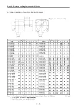
Страница 465: ... servo amplifier can be connected to the SSCNET compatible servo system controller for MR J2S _B_ The MR J4 _B_ RJ020 servo amplifier combined with the MR J4 T20 SSCNET conversion unit can be connected to the SSCNET compatible servo system controller for MR J2S _B_ The MR J4 compatible HG series servo motor can be driven One SSCNET conversion unit is required per amplifier New features of MR J4 ca...

Страница 466: ...onnect the conversion unit to connector CN9 on the side of MR J4 _B_ RJ020 The mounting method for guide pins etc is the same as that for optional MR J3 units such as MR J3 D01 Two SSCNET connectors are provided on the SSCNET conversion unit MR J4 T20 Connected to CN9 CN7 Guide pin CN2L MR J4 _B_ RJ020 ...

Страница 467: ...pply 24 V 100 mA is required for DIO Battery MR BAT A6BAT MR BAT6V1SET Serial communication Half pitch 20 pins miniD Sub Using conversion cable MR J4T20CH00 MR J2S control function Auto Tuning Gain compatibility Model applicable control Machine resonance suppression filter Machine analyzer function Machine simulation Note 1 Gain search function Note 1 Adaptive vibration suppression control Note 1 ...

Страница 468: ...ing Pr 25 to 1_ _ _ _ 1 _ _ or _ 2 _ _ for the MR J4 _B_ RJ020 servo amplifier with software version A8 or earlier will cause AL 37 Parameter error Setting Pr 25 to 1_ _ _ or _ 2 _ _ for the MR J4 _B_ RJ020 servo amplifier with software version A9 or later will cause AL 37 Parameter error The fully closed loop system is enabled only in J2S compatibility mode The fully closed loop system function c...

Страница 469: ...ssary when using MR J4 _B_ RJ020 in J2S compatible mode The application MR J4 W B Change mode or MR Mode Change are available with MR Configurator2 Version 1 27D and later 5 When a servo amplifier other than MR J2S _B_ series MR J2M B series and MR J2 03B5 is used with a controller the MR J4 _B_ RJ020 MR J4 T20 SSCNET conversion unit cannot be used POINT For large capacity of 30 kW or more the pos...

Страница 470: ...Personal computer CN30 Note 5 Setup software SETUP161E Personal computer communication cable RS 232C cable optional Analog monitor 1 10 V DC Analog monitor 2 10 V DC MO1 LG MO2 4 1 14 SD Plate 2 m or less CN8 Note 13 Short circuit connector packed with the servo amplifier 10 m or less 10 m or less Note 3 4 Forced stop Note 6 15 SSCNET cable optional Servo system controller Note 1 CN1B CN1A 24 V DC...

Страница 471: ...M A MR J2S _B_ MR J2 03B5 MR J4 _B_ RJ020 MR J4 T20 MR J2HBUS_M 7 The second and subsequent connections of servo amplifier are omitted 8 Up to 8 axes n 1 to 8 can be connected 9 The CN1 and the CN1B cannot be used in J2S compatible mode Make sure to cap the CN1A and the CN1B connectors 10 Supply 24 V DC 10 from an external power supply for the interface Capacity of these power supplies should be10...

Страница 472: ...ON MANUAL 1 When using adaptive vibration suppression control Refer to 9 2 8 Adaptive vibration suppression control function in this section 2 Changing the load to motor inertia ratio Refer to 9 2 7 Changing the load to motor inertia ratio in this section 6 RS 232C COMMUNICATION CABLE This section indicates the cable connecting the MR J4 T20 and a personal computer through RS 232C communication Th...

Страница 473: ...nector MR J4T20CH00 Connector HDR E14MG1 Connector case HDR E14LPA5 Honda Tsushin Kogyo Connector 10220 0200EL Connector case 10320 E2W0 008 3M 13 12 10 9 8 7 6 5 4 3 2 1 TXD LG LG RXD 11 14 View seen from wiring side Note View seen from wiring side Note Note Do not connect anything to the pins shown as Note Do not connect anything to the pins shown as ...

Страница 474: ...later HC LFS102 MR J4 100B RJ020 A0 or later A0 or later HC LFS152 MR J4 200B RJ020 A0 or later A0 or later HC LFS202 MR J4 350B RJ020 A0 or later A0 or later HC LFS302 MR J4 500B RJ020 A0 or later A0 or later HC SFS 1000 r min series HC SFS81 MR J4 100B RJ020 A0 or later A0 or later HC SFS121 MR J4 200B RJ020 A0 or later A0 or later HC SFS201 MR J4 200B RJ020 A0 or later A0 or later HC SFS301 MR ...

Страница 475: ... HA LFS11K1M MR J4 11KB RJ020 B5 or later A9 or later HA LFS15K1M MR J4 15KB RJ020 B5 or later B4 or later HA LFS22K1M MR J4 22KB RJ020 B5 or later B4 or later HA LFS701M4 MR J4 700B4 RJ020 Not compatible Not compatible HA LFS11K1M4 MR J4 11KB4 RJ020 B5 or later B3 or later HA LFS15K1M4 MR J4 15KB4 RJ020 B5 or later B2 or later HA LFS22K1M4 MR J4 22KB4 RJ020 B5 or later B2 or later HA LFS 2000 r m...

Страница 476: ... MR CR55K MR J4 DU30KB RJ020 Not compatible Not compatible HA LFS37K1M MR J4 DU37KB RJ020 Not compatible Not compatible HA LFS30K1M4 MR CR55K4 MR J4 DU30KB4 RJ020 B5 or later B0 or later HA LFS37K1M4 MR J4 DU37KB4 RJ020 Not compatible Not compatible HA LFS45K1M4 MR J4 DU45KB4 RJ020 A4 or later A4 or later HA LFS50K1M4 MR J4 DU55KB4 RJ020 Not compatible Not compatible HA LFS 2000 r min series HA LF...

Страница 477: ...n series HC SF81 MR J4 100B RJ020 Not compatible A6 or later HC SF121 MR J4 200B RJ020 Not compatible A6 or later HC SF201 Not compatible A6 or later HC SF301 MR J4 350B RJ020 Not compatible A6 or later HC SF 2000 r min series HC SF52 MR J4 60B RJ020 Not compatible A6 or later HC SF102 MR J4 100B RJ020 Not compatible A6 or later HC SF152 MR J4 200B RJ020 Not compatible A6 or later HC SF202 Not com...

Страница 478: ...CPU N Note 1 A0 or later A172SHCPU N Note 1 A173UHCPU S1 Note 1 A273UHCPU S3 Note 1 Positioning module QD75M A1SD75M Note 2 AD75M Note 2 A2 or later AD778M AD774M Not compatible A1SD778M A1SD774M Position board MR MC10 SSCNET II A2 or later MR MC30 Interface board MR MCF30 MR MCF10 A6 or later Note 1 For versions of the OS that supports MR J4 _B_ RJ020 refer to table 8 2 2 Pr 100 servo series of t...

Страница 479: ...N SV13D G or later SW3RN SV22C SW0SRX SV13D AF or later SW0SRX SV22C SW0SRX SV43C T or later A173UHCPU S1 SW3RN SV13B G or later SW3RN SV22A SW2SRX SV13B AF or later SW2SRX SV22A SW2SRX SV43A T or later A273UHCPU SW2SRX SV13V AF or later SW2SRX SV22U SW2SRX SV43U T or later A273UHCPU S3 SW3RN SV13X G or later SW3RN SV22W Table 8 3 Peripheral software versions of motion controllers that support MR ...

Страница 480: ...e torque limit to 500 6 Operation without motor through the setup software SETUP161E cannot be used When operating motor set Pr 24 to _ 1 _ _ 7 When using Pr 13 Position control gain 1 of the MR J4 _B_ RJ020 servo amplifier and the MR J2S _B_ servo amplifier together in interpolation mode etc check the droop pulses of each shaft and readjust the gain as necessary 8 The MR J4 _B_ RJ020 servo amplif...

Страница 481: ...vo motors of the HA_FS and the HC_FS series together regeneration option and external dynamic brake unit can be used with the products used in MR J2S _B_ To change to the HG series servo motor change regeneration option and external dynamic brake unit after referring to the instruction manual for MR J4 _B_ For 1 phase 200 V AC to 240 V AC connect the power supply to L1 and L3 The connection destin...

Страница 482: ... between the MR J4 _B_ RJ020 and the MR J2S _B_ Refer to the table below CN3 connector Pin number Abbreviation Note when replacing from the MR J2S _B_ MR J2S _B_ MR J4 _B_ RJ020 2 RXD For manufacturer setting Do not connect anything to these Connect the RXD to the CN30 connector 13 pin of the MR J4 T20 3 SG DOCOM An external 24 V DC power supply is required for the interface Change the wiring as n...

Страница 483: ... time auto tuning 15 steps Real time auto tuning 40 steps One touch tuning 6 Control mode SSCNET interface Position control mode Speed control mode SSCNET III H interface Position control mode Speed control mode Torque control mode 7 The number of DIO points excluding EM1 SSCNET interface DI 0 points DO 2 points SSCNETⅢ H interface DI 3 points DO 3 points 8 DIO interface Input Sink source Output S...

Страница 484: ...aced with the control circuit power supply turned off When the encoder loses the absolute position data make sure to operate after setting the home position The encoder loses the absolute position data in the following cases It may also lose the absolute position data when the battery is used outside the specified range When the MR BAT6V1SET battery is used Removed the encoder cable Replaced the b...

Страница 485: ...med from the setup software SETUP161E Select Diagnosis Display ABS data and open the absolute position data display screen 5 Connection of battery Connect the battery as shown in the following diagram 6 Gain adjustment When using Pr 13 Position control gain 1 of the MR J4 _B_ RJ020 servo amplifier and the MR J2S _B_ servo amplifier together in interpolation mode etc check the accumulated pulses of...

Страница 486: ...or the load to motor inertia ratio To set the load to motor inertia ratio set _ _ _1 in Pr 59 Option function B and set the ratio calculated by dividing the moment of inertia of the servo motor before replacement by the moment of inertia of the servo motor after replacement in Pr 35 Load to motor inertia ratio in percentage Example When a HC KFS053 motor is replaced with a HG KR053 motor set _ _ _...

Страница 487: ...T The adaptive vibration suppression control function is supported by servo amplifier with software version A9 or later Enabling the adaptive vibration suppression control of Pr 25 of a servo amplifiers with software version A8 or earlier will cause AL 37 Parameter error For the items not described in this Replacement Manual refer to MELSERVO J4 series MR J4 _B_ RJ020 Servo Amplifier Instruction M...

Страница 488: ...ted machine resonance is detected for a maximum of 10 s and a filter is generated After filter generation the adaptive tuning mode automatically shifts to the manual setting Adaptive tuning generates the optimum filter with the currently set control gains Adaptive vibration suppression control may provide no effect on a mechanical system which has complex resonance characteristics This adaptive fi...

Страница 489: ...ect a vibration of 100 Hz or less When the machine resonance does not stop after the vibration tough drive function resets the machine resonance frequency perform the adaptive tuning again This function prevents vibration by resetting a filter instantaneously when machine resonance occurs due to varied vibration frequency caused by equipment aging The vibration tough drive function operates when a...

Страница 490: ...eries MR J4 _B_ RJ020 MR J4 T20 Servo Amplifier Instruction Manual No Symbol Name and function Initial value unit Setting range 25 LPF Low pass filter adaptive vibration suppression control Select a low pass filter adaptive vibration suppression control Refer to section 7 1 2 of MELSERVO J4 series MR J4 _B_ RJ020 MR J4 T20 Servo Amplifier Instruction Manual 0000 Refer to the Name and function colu...

Страница 491: ...r 25 _1 _ _ 0000 0000h to 031Fh Setting digit Explanation Initial value _ _ x x Notch frequency selection Refer to table 5 6 for the setting value 00h _ x _ _ Notch depth selection 0 40 dB 1 14 dB 2 8 dB 3 4 dB 0h x _ _ _ For manufacturer setting 0h Table 5 6 Notch frequency selection Setting value Frequency Hz Setting value Frequency Hz 00 Disabled 10 281 3 01 4500 11 264 7 02 2250 12 250 03 1500...

Страница 492: ...tion warning Warnings are automatically canceled when the cause is removed 96 Home position setting error warning 9F Battery warning E0 Excessive regeneration alarm E1 Overload alarm E3 Absolute position counter alarm E4 Parameter alarm E6 Servo forced stop warning EDB Note 7 E7 Controller emergency stop warning EDB E9 Main circuit off warning DB EE SSCNET error warning Note 1 After the cause of t...

Страница 493: ...e 2 8 mm 200B 350B 97 168 195 90 168 195 7 mm Note 2 3 mm 500B 107 250 200 130 250 200 None 700B 174 300 200 180 350 200 None 11KB 15KB 220 400 260 260 400 260 None 22KB 260 400 260 350 400 260 None DU30KB DU37KB 300 380 300 450 500 300 Note 4 Note 4 60B4 100B4 72 168 195 90 168 195 None 200B4 97 168 195 90 168 195 7 mm Note 2 3 mm 350B4 107 250 200 130 250 200 None 500B4 132 250 200 130 250 200 2...

Страница 494: ... views from the bottom show the increases in width from that of the MR J4 standard model For dimensions when the servo amplifier in different capacities is combined with the MR J4 T20 refer to Appendix 1 11 2 3 Dimensions MR J4 _B_ RJ020 MR J4 T20 11 2 1 Servo amplifier 12mm 7mm 2mm MR J4 10B RJ020 MR J4 T20 MR J4 350B RJ020 MR J4 T20 MR J4 500B RJ020 MR J4 T20 Fig 1 Dimensions ...

Страница 495: ...ppendix 1 Summary of MR J4_B_ RJ020 MR J4 T20 Appendix 1 32 11 2 2 Dimensions MR J4 T20 The dimensions of MR J4 T20 are shown below Fig 2 Dimensions MR J4 T20 For grounding 5 6 mounting hole Rating plate ...

Страница 496: ... MR J2S 40B_ MR J2S 60B C E N A 70 135 TE1 TE2 4 B PE terminal 168 7 6 6 156 OPEN U V W L1 L2 L3 MITSUBISHI 20 Rating plate OPEN Terminal layout diagram Upper part of body with terminal opened MITSUBISHI 6 C A N 1 C N 2 C N 1 B C N 3 E N C C A N 1 C C N 2 N 1 B C N 3 Servo amplifier Variable dimensions Mass kg A B MR J2S 40B 1 70 22 1 1 MR J2S 60B MR J4 40B RJ020 MR J4 60B RJ020 φ 6 mounting hole ...

Страница 497: ...J020 φ6 mounting hole Exhaust Cooling fan intake MR BAT6V1SET mounted MR J2S 350B Servo amplifier Mass kg MR J2S 350B 2 0 MR J4 350B RJ020 mounting hole MR BAT6V1SET mounted Cooling fan intake Exhaust MR J2S 500B Servo amplifier Mass kg MR J2S 500B 4 9 MR J4 500B RJ020 2 φ6 mounting hole MR BAT6V1SET mounted Intake Cooling fan exhaust MR J2S 700B Servo amplifier Mass kg MR J2S 700B 7 2 MR J4 700B ...

Страница 498: ... J2S 11KB 15 MR J2S 15KB 16 MR J4 11KB RJ020 MR J4 15KB RJ020 2 φ6 mounting hole Cooling fan exhaust MR BAT6V1SET mounted Intake MR J2S 22KB 75 CN4 C N 3 C N 1 A C N 1 B MI TSU B ISH I TE1 CON2 12 326 376 400 12 350 12 12 12 CHARGE CN2 TE2 3 9 260 Cooling fan Intake Blowing direction of cooling fan Servo amplifier Mass kg MR J2S 22KB 20 MR J4 22KB RJ020 260 400 12 12 12 236 260 188 5 223 4 235 4 3...

Страница 499: ... cover Intake MR J4 DU30KB RJ020 MR J4 DU37KB RJ020 100 180 155 300 380 360 10 20 CN40A 260 200 175 5 178 5 22 5 22 32 118 62 15 5 92 11 41 59 124 5 24 195 80 TE2 1 TE2 2 TE1 PE TE3 7 20 10 10 130 1 162 5 31 28 Intake 2 φ7 mounting hole MR BAT6V1SET mounted Cooling fan exhaust MR HP30KA 2 φ12 mounting hole Safety cover Cooling fan exhaust Intake MR CR55K 2 φ7 mounting hole Cooling fan exhaust Inta...

Страница 500: ...R J2S 60B4 MR J2S 100B4 MR J4 60B4 RJ020 MR J4 100B4 RJ020 φ6 mounting hole MR BAT6V1SET mounted MR J2S 200B4 MR J4 200B4 RJ020 φ6 mounting hole MR BAT6V1SET mounted Cooling fan intake MR J2S 350B4 2 φ6 mounting hole Terminal layout diagram Fan Fan Blowing direction of cooling fan TE2 MR J4 350B4 RJ020 2 φ6 mounting hole Cooling fan exhaust MR BAT6V1SET mounted Intake ...

Страница 501: ...ve resistor Screw for securing lead terminal Screw size M4 Tightening torque 1 2 N m MR J2S 700B4 2 φ6 mounting hole Terminal layout diagram Fan Blowing direction of cooling fan MR J4 700B4 RJ020 Cooling fan exhaust MR BAT6V1SET mounted Intake Built in regenerative resistor Screw for securing lead terminal Screw size M4 Tightening torque 1 2 N m 2 φ6 mounting hole MR J2S 11KB4 MR J2S 15KB4 3 9 260...

Страница 502: ...ole Cooling fan exhaust Safety cover Note Intake MR J4 DU30KB4 RJ020 180 100 360 10 60 CN40A 120 155 380 240 175 5 178 5 22 5 22 38 105 5 143 56 92 52 11 41 124 5 24 200 195 60 10 6 10 TE2 TE1 PE TE3 80 170 5 152 5 28 28 2 φ6 mounting hole Cooling fan exhaust Intake MR BAT6V1SET mounted MR J2S 37KB4 2 φ12 mounting hole Cooling fan exhaust Safety cover Note Intake MR J4 DU37KB4 RJ020 180 100 360 10...

Страница 503: ...ver Note Intake MR J4 DU45KB4 RJ020 MR J4 DU55KB4 RJ020 100 180 155 300 380 360 10 20 CN40A 260 200 175 5 178 5 22 5 22 32 118 62 15 5 92 11 41 59 124 5 24 195 80 TE2 1 TE2 2 TE1 PE TE3 7 20 10 10 130 1 162 5 31 28 2 φ7 mounting hole MR BAT6V1SET mounted Intake Cooling fan exhaust MR HP55KA4 2 φ12 mounting hole Safety cover Cooling fan exhaust Intake MR CR55K4 2 φ7 mounting hole Cooling fan exhaus...

Страница 504: ...ystem Compatible Not compatible Fully closed loop system Compatible Not compatible 12 1 Mode Switching Method from J2S Compatibility Mode to J4 Mode 1 Turn on the servo amplifier with the MR J4 T20 removed 2 Run the application of MR J4 W B Change mode or MR Mode Change and verify that J2S Compatibility Mode is not displayed in Compatibility Mode If displayed try again from 1 of this section 3 Sel...

Страница 505: ... J2S Compatibility mode is displayed in Compatibility Mode If not try again from 1 of this section 3 Select Switch mode and then choose J2S compatibility mode Only standard control mode can be selected for the operation mode 4 Click the Write button 5 By cycling the power supply of the servo amplifier the mode will switch to J2S compatibility mode POINT For the details of the parameters refer to M...

Страница 506: ...rvo amplifier For details of the options for the servo amplifier refer to Chapter 11 of the MR J4 _B_ RJ020 MR J4 T20 Servo Amplifier Instruction Manual For options for the HC _FS series and the HA _FS series servo motors refer to MR J2S _B Servo Amplifier Instruction Manual SH NA 030007 and MELSERVO Servo Motor Instruction Manual SH NA 3181 POINT Protection grades shown on the cable and the conne...

Страница 507: ... ELECTRIC INDUSTRIAL CO LTD IP20 5 Encoder cable MR JCCBL_M H Cable length 2 5 10 20 30 40 50 m IP20 Long bending life 6 Encoder cable MR ESCBL_M L Cable length 2 5 10 20 30 m For details refer to section 13 3 3 IP20 7 Encoder cable MR ESCBL_M H Cable length 2 5 10 20 30 40 50 m IP20 Long bending life 8 Encoder cable MR JHSCBL_M L Cable length 2 5 10 20 30 m Connector 10120 3000PE Shell kit 10320 ...

Страница 508: ...o _ 1 _ _ and select four wires system Incorrect setting will cause AL 16 Encoder Error 1 1 MR EKCBL_M _ These cables are encoder cables for the HC KFS HC MFS and HC UFS 3000 r min servo motors The numbers in the cable length field of the table indicate the symbol filling the underline _ in the cable model The cables of the lengths with the symbols are available Cable model Cable length Protection...

Страница 509: ...lamp MTI 0002 TOA ELECTRIC INDUSTRIAL CO LTD MR EKCBL_M H Note Do not connect anything to the pins shown as Especially 10 pin is for manufacturer adjustment Connection to other pins will cause the servo amplifier to operate abnormally MRR LG P5 MR BAT MDR MD P5 MR BAT MRR LG MDR MD 1 3 7 9 4 2 8 6 10 5 4 2 8 6 1 5 10 3 7 9 or View seen from wiring side Note View seen from wiring side Note MR 1 2 3...

Страница 510: ...necessary to wire Encoder connector CN2 connector Note Plate P5 LG 1 2 MR MRR 3 4 MDR 8 5 3 7 4 MD 7 9 SD 1 2 8 9 LG MR MRR MDR MD SHD P5 6 CONT BAT BAT Encoder connector CN2 connector Note Plate P5 LG 1 2 MR MRR 3 4 3 7 9 SD 1 2 8 9 LG MR MRR SHD P5 BAT BAT Encoder connector CN2 connector Note P5 LG 1 2 MR MRR 3 4 MDR 8 5 3 7 4 MD 7 9 SD 1 2 8 9 LG MR MRR MDR MD SHD P5 6 CONT BAT BAT Plate P5 LG ...

Страница 511: ...onnection Cable model 1 CN2 connector 2 Relay connector MR J3CH00 Receptacle 36210 0100PL Shell kit 36310 3200 008 3M Connector set 54599 1019 Molex Connector 10220 0200EL Shell kit 10320 E2W0 008 3M Note Do not connect anything to the pins shown as Especially 10 pin is for manufacturer adjustment Connection to other pins will cause the servo amplifier to operate abnormally Note Do not connect any...

Страница 512: ...te When using the absolute position detection system make sure to connect When using the incremental system it is not necessary to wire P5 LG 1 2 MR MRR 3 4 MDR 8 16 9 19 6 MD 7 9 SD 7 17 11 LG MR MRR MDR MD SD P5 1 LG BAT BAT 20 12 18 2 LG P5 LG P5 Encoder connector CN2 connector Note Plate Plate ...

Страница 513: ...er servo motor connection Cable model 1 CN2 connector 2 Encoder connector MR ESCBL_M L Receptacle 36210 0100PL Shell kit 36310 3200 008 3M Connector set 54599 1019 Molex Plug D MS3106B20 29S Cable clamp D MS3057 12A DDK Ltd Note Do not connect anything to the pins shown as Especially 10 pin is for manufacturer adjustment Connection to other pins will cause the servo amplifier to operate abnormally...

Страница 514: ...nnector Note Plate P5 LG 1 2 MR MRR 3 4 F S 9 SD C D R N LG MR MRR SHD P5 BAT BAT Encoder connector CN2 connector Note Plate P5 LG 1 2 MR MRR 3 4 MDR 8 B F S A MD 7 9 SD C D R N LG MR MRR MDR MD SHD P5 M CONT BAT BAT Encoder connector CN2 connector Note Plate F S C D R N P5 LG 1 2 MR MRR 3 4 9 SD LG MR MRR SHD P5 BAT BAT F S C D R N P5 LG 1 2 MR MRR 3 4 9 SD LG MR MRR SHD P5 BAT BAT Encoder connec...

Страница 515: ...position detection system make sure to connect When using the incremental system it is not necessary to wire Encoder connector CN2 connector Note Plate P5 LG 1 2 MR MRR 3 4 MDR 8 B F S A MD 7 9 SD C D R N LG MR MRR MDR MD SHD P5 M CONT BAT BAT Encoder connector CN2 connector Note Plate P5 LG 1 2 MR MRR 3 4 F S 9 SD C D R N LG MR MRR SHD P5 BAT BAT ...

Страница 516: ...ection 13 4 2 Connector 10120 3000PE Shell kit 10320 52F0 008 3M or equivalent Connector PCR S20FS Case PCR LS20LA1 HONDA TSUSHIN KOGYO CO LTD 2 Connector set MR J2CN1 A Refer to section 13 4 2 Connector 10120 3000PE Shell kit 10320 52F0 008 3M or equivalent Connector PCR S20FS Shell kit PCR LS20LA1 HONDA TSUSHIN KOGYO CO LTD 3 Electromagnetic contactor wiring connector Connector on the converter ...

Страница 517: ...xpected motion This cable is intended to connect the converter unit and the drive unit 1 Internal wiring diagram MR J3CDL05M 1 11 2 12 3 13 4 14 5 15 6 16 7 17 8 18 9 19 10 20 1 11 2 12 3 13 4 14 5 15 6 16 7 17 8 18 9 19 10 20 ACD2 ACD2 ACD3 ACD3 PAL PAL ACD1 ACD1 LG LG GOF GOF PMC PMC PSD PSD LG LG PRD PRD SD 10120 3000PE Connector 10320 52F0 008 Shell kit PCR S20FS Connector PCR LS20LA1 Case Con...

Страница 518: ...500 MR J4 500B RJ020 130 300 500 MR J4 700B RJ020 170 300 500 MR J4 11KB RJ020 MR J4 15KB RJ020 MR J4 22KB RJ020 MR J4 DU30KB RJ020 MR J4 DU37KB RJ020 Servo amplifier model Built in regenerative resistor W Note 2 MR J2S standard accessories External Permissible regenerative power of regenerative option W MR RB Note 2 5R 3 2 Ω Note 2 65 8 Ω Note 2 66 5 Ω Note 2 67 4 Ω Note 2 9F 3 Ω Note 2 9T 2 5 Ω ...

Страница 519: ...ote 2 65 8 Ω Note 2 66 5 Ω Note 2 67 4 Ω Note 2 9F 3 Ω Note 2 9T 2 5 Ω 139 1 3 Ω Note 5 137 1 3 Ω MR J4 10B 1 RJ020 MR J4 20B 1 RJ020 10 MR J4 40B 1 RJ020 10 MR J4 60B RJ020 10 MR J4 70B RJ020 20 MR J4 100B RJ020 20 MR J4 200B RJ020 100 MR J4 350B RJ020 100 MR J4 500B RJ020 130 MR J4 700B RJ020 170 MR J4 11KB RJ020 GRZG400 0 8Ω 4 500 800 500 800 MR J4 15KB RJ020 GRZG400 0 6Ω 5 850 1300 850 1300 MR...

Страница 520: ...0 Servo amplifier model Built in regenerative resistor W Note 2 MR J2S standard accessories External Permissible regenerative power of regenerative option W MR RB Note 2 5K 4 10 Ω Note 2 6B 4 20 Ω Note 2 60 4 12 5 Ω Note 2 6K 4 10 Ω 136 4 5 Ω Note 3 138 4 5 Ω MR J4 60B4 RJ020 15 Note 4 MR J4 100B4 RJ020 15 Note 4 MR J4 200B4 RJ020 100 MR J4 350B4 RJ020 100 MR J4 500B4 RJ020 130 MR J4 700B4 RJ020 1...

Страница 521: ...2 6B 4 20 Ω Note 2 60 4 12 5 Ω Note 2 6K 4 10 Ω 137 4 4 Ω Note 4 13V 4 4 Ω MR J4 60B4 RJ020 15 Note 5 MR J4 100B4 RJ020 15 Note 5 MR J4 200B4 RJ020 100 MR J4 350B4 RJ020 100 MR J4 500B4 RJ020 130 MR J4 700B4 RJ020 170 MR J4 11KB4 RJ020 GRZG400 2 5Ω 4 500 800 500 800 MR J4 15KB4 RJ020 GRZG400 2Ω 5 850 1300 850 1300 MR J4 22KB4 RJ020 GRZG400 2Ω 5 850 1300 850 1300 MR J4 DU30KB4 RJ020 1300 3900 MR J4...

Страница 522: ...9 55 10 4 JL η JM V tpsa1 1 TU TF E1 2 0 1047 V T1 tpsa1 2 T2 TU TF E2 0 1047 V T2 t1 3 T3 9 55 104 JL η JM V tpsa2 1 TU TF E3 2 0 1047 V T3 tpsa2 4 8 T4 T8 TU E4 E8 0 no regeneration 5 T5 9 55 10 4 JL η JM V tpsd2 1 TU TF E5 2 0 1047 V T5 tpsd2 6 T6 TU TF E6 0 1047 V T6 t3 7 T7 9 55 104 JL η JM V tpsd2 1 TU TF E7 2 0 1047 V T7 tpsd2 Determine the absolute value Es of the total sum of negative ene...

Страница 523: ... 20B1 RJ020 75 4 MR J4 15KB RJ020 90 170 MR J4 40B1 RJ020 85 10 MR J4 22KB RJ020 90 250 Converter unit Drive unit Motor inverse efficiency C charge J MR CR55K MR J4 DU30KB RJ020 90 450 MR J4 DU37KB RJ020 90 450 MR CR55K 4 MR J4 DU30KB4 RJ020 90 450 MR J4 DU37KB4 RJ020 90 450 MR J4 DU45KB4 RJ020 90 450 MR J4 DU55KB4 RJ020 90 450 Inverse efficiency η Efficiency including part of the servo motor and ...

Страница 524: ...eeded 0E When increasing the capabilities by using a cooling fan to cool the supplied regeneration resistor with the servo amplifier of 11 kW to 22 kW 10 MR RB032 11 MR RB12 13 MR RB5E 14 MR RB5E Cooling fan is needed 17 MR RB9F 18 MR RB9F Cooling fan is needed 20 MR RB3N 21 MR RB5N Cooling fan is needed 23 MR RB5R 24 24 MR RB5R Cooling fan is needed 25 MR RB9P 26 MR RB9P Cooling fan is needed 27 ...

Страница 525: ...ermal sensors Abnormal overheating of the regenerative option causes the contact between G3 and G4 to open Note 1 When using MR RB50 MR RB3M 4 MR RB3G 4 MRRB5G 4 MR RB3H 4 and MR RB5H 4 perform forced cooling using the cooling fan 1 0 m3 min or more 92 mm square 2 Provide forced cooling for MR RB30 MR RB31 and MR RB32 using the cooling fan 1 0 min or more 92 mm square when the ambient temperature ...

Страница 526: ...onfigure sequence of shutting off the electromagnetic contactor when abnormal heating is caused Specifications for contacts between G3 and G4 Maximum voltage 120 V AC DC Maximum current 0 5 A 4 8 V DC Maximum capacity 2 4 VA When you use the regenerative option remove the wiring between P and C for the regenerative resistor built into the servo amplifier place back to back as shown in the diagram ...

Страница 527: ... min or more 92 mm square x 2 pcs enhances regenerative power In this case set Pr 2 to _ _ 0 E Note The number of series connections varies depending on the type of resistors Thermal sensors are not built into the supplied regenerative resistors In the case of a failure of the regenerative circuit the possible cause is abnormal overheating of resistors Therefore you should install thermal sensors ...

Страница 528: ...G4 Maximum voltage 120 V AC DC Maximum current 0 5 A 4 8 V DC Maximum capacity 2 4 VA Servo amplifier Regenerative options Resistance value Ω Regenerative power W Without cooling fan With cooling fan MR J4 11KB RZ020 MR RB5E 6 500 800 MR RB5R 3 2 MR J4 15KB RZ020 MR RB9P 4 5 850 1300 MR RB9F 3 MR J4 22KB RZ020 MR RB9T 2 5 850 1300 MR J4 11KB4 RZ020 MR RB5K 4 10 500 800 MR RB6B 4 20 MR J4 15KB4 RZ0...

Страница 529: ...ing contact between the wires and the regenerative option The G3 and the G4 terminals are thermal protectors Abnormal overheating of the regenerative option causes the contact between G3 and G4 to open Be sure to use twisted wires when connecting to the converter unit and keep the wiring distance to no longer than 5 m 1 MR RB139 MR RB137 4 Note 1 When using the power factor improving DC reactor re...

Страница 530: ... more combination is shown below Name Compatible MR J4 B MR J2S B MR J4 B RJ020 HG motor Drive HA _FS HC _FS motor Drive HA _FS HC _FS motor Drive HG motor Drive HA _FS HC _FS motor Drive DBU 37K Not compatible Compatible Compatible Not compatible Compatible DBU 37K R1 Compatible Not compatible Not compatible Compatible Not compatible DBU 55K 4 Not compatible Compatible Compatible Not compatible C...

Страница 531: ...rom the motion controller in J2S Compatibility Mode 14 1 Combination of Motion Controller and Peripheral Software Series Motion controller model Motion controller peripheral software Q series Q172CPU N Q173CPU N MELSOFT MT Works2 SW1DNC MTW2 E MT Developer SW6RNC GSVE A series A171SHCPU N A172SHCPU N A173UHCPU A273UHCPU SW3RNC GSVE 14 2 Parameter Setting Procedure 14 2 1 For MELSOFT MT Works2 1 Di...

Страница 532: ...alues are shown below a Change of Pr 2 regenerative resistor hexadecimal parameter To change the setting value to 0020 enter 0020 as it is b Change of Pr 12 load inertia moment ratio relative to the servo motor load inertia ratio decimal parameter To change the setting value to 7 0 enter 0046 which is the value resulted from converting 70 to the hexadecimal number c Change of Pr 39 Electronic dyna...

Страница 533: ... Appendix 1 Summary of MR J4_B_ RJ020 MR J4 T20 Appendix 1 70 4 Write the changed parameter in communication Clicking Execute will run a write Click ...

Страница 534: ... 2 2 For MT Developer software version 00W or later 1 Display the Servo data setting window 2 Double click the setting field 1 to 75 under special parameters Parameter No in the Servo parameter tab and display the Servo special parameter setting dialog Double click ...

Страница 535: ...g value to 0020 enter 0020 as it is b Change of Pr 12 load inertia moment ratio relative to the servo motor load inertia ratio decimal parameter To change the setting value to 7 0 enter 0046 which is the value resulted from converting 70 to the hexadecimal number c Change of Pr 39 Electronic dynamic brake operating time decimal parameter To change the setting value to 10000 enter 2710 which is the...

Страница 536: ...he steps during communication with the servo controller and the servo amplifier 1 Setting procedure a Display the monitor screen Set the monitor to a stooped state of monitor using the positioning monitor a With the monitor screen displayed use the shortcut keys Ctrl Shift Alt O on the keyboard to display the Servo special parameter setting dialog ...

Страница 537: ... enter 0020 as it is b Change of Pr 12 load inertia moment ratio relative to the servo motor load inertia ratio decimal parameter To change the setting value to 7 0 enter 0046 which is the value resulted from converting 70 to the hexadecimal number c Change of Pr 39 Electronic dynamic brake operating time decimal parameter To change the setting value to 10000 enter 2710 which is the value resulted...

Страница 538: ...uction to Renewal Tool Mitsubishi Electric System Service Co Ltd www melsc co jp business OVERSEAS SERVICE SUPPORT SECTION Email osb webmaster melsc jp Mitsubishi Electric System Service Co Ltd provides the related services For details please refer to the following address ...

Страница 539: ... RJ MR J4 _A1 RJ 1 2 Features It is possible to operate the exiting MR J2S servo motor with the MR J4 servo amplifier Wiring work can be shortened because the existing cables can be connected as they are except for some models The renewal kit can be mounted using the existing mounting holes The existing space can be effectively used by adopting the sliding mechanism for the renewal kit For some mo...

Страница 540: ... motor for MR J2S Before replacement After replacement Primary replacement When replacing the servo amplifier only Servo motor for MR J2S Secondary replacement When replacing the servo motor after replacing the servo amplifier Simultaneous replacement When replacing the servo amplifier and the servo motor simultaneously Servo motor for MR J4 ...

Страница 541: ... J2S Before replacement After replacement Primary replacement When replacing the servo amplifier only Servo motor for MR J2S Secondary replacement When replacing the servo motor after replacing the servo amplifier Simultaneous replacement When replacing the servo amplifier and the servo motor simultaneously Servo motor for MR J4 ...

Страница 542: ...minal block For 200 V 0 1 kW to 3 5 kW Plug in type connector 5 kW or more Terminal block For 400 V 0 6 kW to 3 5 kW Plug in type connector 5 kW or more Terminal block For 200 V With terminal block conversion Note 19 Main circuit power supply terminal connection method For 200 V Terminal block For 400 V 0 6 kW to 2 kW Plug in type connector 3 5 kW or more Terminal block For 200 V 0 1 kW to 3 5 kW ...

Страница 543: ...l Connector 7 kW or less Control signal CN1A CN1B 2 pcs Encoder signal CN2 1 unit Monitor signal CN3 1 unit Control signal CN1 1 unit Encoder signal CN2 1 unit Monitor signal CN6 1 unit Different connector shape With conversion cable Compatible 11 kW to 55 kW Control signal CN1A CN1B 2 pcs Encoder signal CN2 1 pcs Communication connector CN3 1 pcs Monitor signal CN4 1 pcs Note 20 Maximum input pul...

Страница 544: ...S 232C Push button MR Configurator2 Communication method USB Push button Note 13 RS 422 232C communication function RS 422 232C serial communication function RS 422 serial communication function Unsupported Note 14 Analog monitor input Input 2 ch 10 bit torque 14 bit speed or equivalent Input 2 ch 10 bit torque 14 bit speed or equivalent Analog monitor output 2 ch 0 to 10 V 10 bit resolution or eq...

Страница 545: ...maximum Note 8 Forced stop EM1 DB stop Forced stop EM1 DB stop Possible to select EM2 deceleration stop Note 9 DO signal 2 points 3 points DIO interface Input Sink source Output Sink Input Output Sink source Encoder pulse output ABZ phase differential line driver ABZ phase differential line driver Note 12 Parameter setting method Setup software SETUP161E Communication method RS 232C Setup software...

Страница 546: ...ted Note 11 DI DO combination 1 points 0 points Unsupported Note 22 DIO interface Input Sink source Output Sink Input Output Sink source Number of internal speed commands 7 points 7 points Encoder pulse output ABZ phase differential line driver Z phase open collector ABZ phase differential line driver Z phase open collector Note 12 Parameter setting method Setup software SETUP161E Communication me...

Страница 547: ...al purpose interfaces Part 3 for SSCNET interfaces and Part 4 for built in positioning For built in positioning it is not able to change the assignment of the forced stop signal CN1 42 pin by the parameter in the MR J4 servo amplifier When the assignment of the EMG signal in the existing MR J2S servo amplifier has been changed the existing wiring change becomes necessary 10 This is the time until ...

Страница 548: ...ifferent connector shape With conversion cable HC MFS HG MR different connector shape HC SFS HG SR different connector shape Note 1 HC RFS HG RR HC LFS HG JR different connector shape Note 1 HC UFS B 2000 r min HG UR HC UFS B 3000 r min HG KR different connector shape HA LFS 7 kW or less HG SR different connector shape HA LFS 11 kW or more HG JR different connector shape Note 2 Note 3 Note 4 Note ...

Страница 549: ...he MR J2S monitor signal is changed for MR J4 Control signal conversion cable The MR J2S encoder signal is changed for MR J4 Encoder conversion cable The MR J2S encoder signal is changed for MR J4 Control circuit power supply conversion terminal block Note 3 Connects to the existing control circuit power supply and regenerative option Main circuit power supply conversion terminal block Note 3 Conn...

Страница 550: ...rsion cable Note 2 The MR J2S encoder signal is changed for MR J4 Encoder conversion cable The MR J2S encoder signal is changed for MR J4 Control circuit power supply conversion terminal block Note 3 Connects to the existing control circuit power supply and regenerative option Main circuit power supply conversion terminal block Note 3 Connects to the existing main circuit power supply and servo mo...

Страница 551: ...ing cable To programmable controller Power supply conversion terminal block Encoder conversion cable Existing encoder cable Encoder Conversion cable on the motor side Existing power supply cable Existing brake cable Power supply conversion cable on the motor side Brake conversion cable on the motor side Electromagnetic brake power supply Servo motor for MR J4 MR J4 _A_ RJ Servo amplifier Renewal k...

Страница 552: ...r conversion cable Existing cable Existing encoder cable Existing brake cable Existing power supply cable Existing electromagnetic brake power supply Servo motor for MR J2S Rear axle servo amplifier Renewal kit MR J4 _B_ RJ020 MR J4 T20 Existing SSCNET cable Servo system controller or front servo amplifier Rear axle servo amplifier To programmable controller 24 V DC power supply connection connect...

Страница 553: ... MR J4 _B_ RJ020 servo amplifier capacity For 400 W 600 W 3 SC J2SBJ4KT1K MR J4 _B RJ020 amplifier capacity For 700 W 1 kW 4 SC J2SBJ4KT3K MR J4 _B RJ020 servo amplifier capacity For 2 kW 3 5 kW 5 SC J2SBJ4KT5K MR J4 _B RJ020 servo amplifier capacity For 5 kW 6 SC J2SBJ4KT7K MR J4 _B RJ020 servo amplifier capacity For 7 kW 7 SC J2SBJ4KT15K MR J4 _B RJ020 servo amplifier capacity For 11 kW 15 kW 8 ...

Страница 554: ...020 servo amplifier capacity For 2 kW 5 SC J2SJ4BS04 MR J4 _A servo amplifier capacity For 5 kW MR J4 _B RJ020 servo amplifier capacity For 5 kW 6 MR J4 _A4 servo amplifier For 3 5 kW MR J4 _B4 RJ020 servo amplifier For 3 5 kW 7 SC J2SJ4BS05 MR J4 _A servo amplifier capacity For 7 kW MR J4 _B RJ020 servo amplifier capacity For 7 kW 8 MR J4 _A4 servo amplifier capacity For 7 kW MR J4 _B4 RJ020 serv...

Страница 555: ...tions inertia load etc there is a possibility of insufficient servo amplifier capacity after replacement Carefully consider the capacity in relation to the replacement 8 Although use of dynamic brake resistance standardly equipped to the replacement MR J4 servo amplifier is possible take care because the coasting distance differs depending on the characteristics of the dynamic brake In addition do...

Страница 556: ...bination list in Section 4 1 to 4 5 Select the renewal kit from column 3 of the replacement combination list in Section 4 1 to 4 5 2 Secondary replacement menu Check the combination of the existing servo motor model or of the existing models Select the secondary replacement models from column 2 and 4 of the replacement combination list in Section 4 1 to 4 5 Select the renewal kit from column 3 and...

Страница 557: ...eck the combination of the existing servo motor model or of the existing models Select the secondary replacement models from column 4 and 5 of the replacement combination list in Section 4 1 to 4 5 Select the renewal kit from column 6 and the motor side conversion cable from column 7 of the replacement combination list in Section 4 1 to 4 5 3 Simultaneous replacement menu Check the combination of ...

Страница 558: ... HC KFS13 B G1 1 5 HG KR13 B G1 1 5 HC KFS13 B G1 1 12 HG KR13 B G1 1 12 HC KFS13 B G1 1 20 HG KR13 B G1 1 20 MR J2S 20A 1 HC KFS23 B G1 1 5 MR J4 20A 1 HG KR23 B G1 1 5 HC KFS23 B G1 1 12 HG KR23 B G1 1 12 Note 2 HC KFS23 B G1 1 20 HG KR23 B G1 1 20 Note 2 MR J2S 40A 1 HC KFS43 B G1 1 5 MR J4 40A 1 SC J2SJ4KT06K HG KR43 B G1 1 5 HC KFS43 B G1 1 12 HG KR43 B G1 1 12 Note 2 HC KFS43 B G1 1 20 HG KR...

Страница 559: ... B G5 1 11 HG KR43 B G5 1 11 HC KFS43 B G5 1 21 HG KR43 B G5 1 21 HC KFS43 B G5 1 33 HG KR43 B G5 1 33 HC KFS43 B G5 1 45 HG KR43 B G5 1 45 MR J2S 70A HC KFS73 B G5 1 5 MR J4 70A SC J2SJ4KT1K HG KR73 B G5 1 5 HC KFS73 B G5 1 11 HG KR73 B G5 1 11 HC KFS73 B G5 1 21 HG KR73 B G5 1 21 HC KFS73 B G5 1 33 HG KR73 B G5 1 33 HC KFS73 B G5 1 45 HG KR73 B G5 1 45 Small capacity low inertia HC KFS series wi...

Страница 560: ...odel Servo amplifier model Note 1 Servo motor model Note 1 Renewalkit model Motor side conversion cable model Compatibility Power supply conversion cable Encoder conversion cable Brake conversion cable Small capacity low inertia HC KFS series standard with brake B represents models with brake MR J2S 70A HC KFS46 MR J4 70A Note 10 SC J2SJ4KT1K MR J4 40A Note 10 HG KR43 Note 4 Note 15 Note 11 Withou...

Страница 561: ... HG KR13 B G1 1 12 HC MFS13 B G1 1 20 HG KR13 B G1 1 20 MR J2S 20A 1 HC MFS23 B G1 1 5 MR J4 20A 1 HG KR23 B G1 1 5 HC MFS23 B G1 1 12 HG KR23 B G1 1 12 Note 2 HC MFS23 B G1 1 20 HG KR23 B G1 1 20 Note 2 MR J2S 40A 1 HC MFS43 B G1 1 5 MR J4 40A 1 SC J2SJ4KT06K HG KR43 B G1 1 5 HC MFS43 B G1 1 12 HG KR43 B G1 1 12 Note 2 HC MFS43 B G1 1 20 HG KR43 B G1 1 20 Note 2 MR J2S 70A HC MFS73 B G1 1 5 MR J4...

Страница 562: ...S43 B G5 1 11 HG KR43 B G5 1 11 HC MFS43 B G5 1 21 HG KR43 B G5 1 21 HC MFS43 B G5 1 33 HG KR43 B G5 1 33 HC MFS43 B G5 1 45 HG KR43 B G5 1 45 MR J2S 70A HC MFS73 B G5 1 5 MR J4 70A SC J2SJ4KT1K HG KR73 B G5 1 5 HC MFS73 B G5 1 11 HG KR73 B G5 1 11 HC MFS73 B G5 1 21 HG KR73 B G5 1 21 HC MFS73 B G5 1 33 HG KR73 B G5 1 33 HC MFS73 B G5 1 45 HG KR73 B G5 1 45 Small capacity low inertia HC MFS series...

Страница 563: ...R702 B Existing cable can be used Medium capacity medium inertia HC SFS series with high precision reducer G2 B represents models with brake MR J2S 60A HC SFS52 B G2 1 5 MR J4 60A SC J2SJ4KT06K HG SR52 B G7 1 5 Note 3 Note 6 SC SAJ3PW2KC1M S2 SC HAJ3ENM3C1M Note 7 HC SFS52 B G2 1 9 HG SR52 B G7 1 11 HC SFS52 B G2 1 20 HG SR52 B G7 1 21 HC SFS52 B G2 1 29 HG SR52 B G7 1 33 HC SFS52 B G2 1 45 HG SR5...

Страница 564: ...G SR102 B G1 H 1 59 MR J2S 200A HC SFS152 B G1 H 1 6 MR J4 200A SC J2SJ4KT3K HG SR152 B G1 H 1 6 HC SFS152 B G1 H 1 11 HG SR152 B G1 H 1 11 HC SFS152 B G1 H 1 17 HG SR152 B G1 H 1 17 HC SFS152 B G1 H 1 29 HG SR152 B G1 H 1 29 HC SFS152 B G1 H 1 35 HG SR152 B G1 H 1 35 HC SFS152 B G1 H 1 43 HG SR152 B G1 H 1 43 HC SFS152 B G1 H 1 59 HG SR152 B G1 H 1 59 HC SFS202 B G1 H 1 6 HG SR202 B G1 H 1 6 SC H...

Страница 565: ...5 1 45 MR J2S 350A HC SFS352 B G5 1 5 MR J4 350A HG SR352 B G5 1 5 HC SFS352 B G5 1 11 HG SR352 B G5 1 11 HC SFS352 B G5 1 21 HG SR352 B G5 1 21 MR J2S 500A HC SFS502 B G5 1 5 MR J4 500A SC J2SJ4KT5K HG SR502 B G5 1 5 HC SFS502 B G5 1 11 HG SR502 B G5 1 11 MR J2S 700A HC SFS702 B G5 1 5 MR J4 700A SC J2SJ4KT7K HG SR702 B G5 1 5 Existing cable can be used Medium capacity medium inertia HC SFS serie...

Страница 566: ...RFS series with high precision reducer G2 B represents models with brake MR J2S 200A HC RFS103 B G2 1 5 MR J4 200A Note 10 SC J2SJ4KT3K MR J4 100A Note 10 HG SR102 B G7 1 5 Note 3 Note 4 Note 11 SC SAJ3PW2KC1M S2 SC HAJ3ENM3C1M Note 7 HC RFS103 B G2 1 9 HG SR102 B G7 1 11 HC RFS103 B G2 1 20 HG SR102 B G7 1 21 HC RFS103 B G2 1 29 HG SR102 B G7 1 33 HC RFS103 B G2 1 45 HG SR102 B G7 1 45 HC RFS153 ...

Страница 567: ...R202 B G5 1 45 MR J2S 500A HC RFS353 B G5 1 5 MR J4 500A Note 10 SC J2SJ4KT5K MR J4 350A Note 10 HG SR352 B G5 1 5 Note 11 SC HAJ3PW1C1M HC RFS353 B G5 1 11 HG SR352 B G5 1 11 HC RFS353 B G5 1 21 HG SR352 B G5 1 21 HC RFS353 B G5 1 33 HC RFS503 B G5 1 5 MR J4 500A MR J4 500A HG SR502 B G5 1 5 SC J2SJ4KT5K HC RFS503 B G5 1 11 HG SR502 B G5 1 11 HC RFS503 B G5 1 21 Medium capacity ultra low inertia ...

Страница 568: ... power supply conversion cable MR J2S 20A 1 HC UFS23 B MR J4 20A 1 HG KR23 B MR J2S 40A 1 HC UFS43 B MR J4 40A 1 SC J2SJ4KT06K HG KR43 B MR J2S 70A HC UFS73 B MR J4 70A SC J2SJ4KT1K HG KR73 B Refer to Appendix page 2 65 for important points to note 12 Existing HC LFS motor series Compatible Limited functions or compatible with certain conditions Incompatible 1 2 3 4 5 6 7 Existing model Note 13 Pr...

Страница 569: ...els with brake MR J2S 700A HA LFS701M B Note 16 MR J4 700A HG JR701M B Note 4 Note 3 SC J2SJ4KT7K SC J2SJ4PW3C1M Existing cable can be used Existing brake cable can be used Cooling fan cable Note 9 MR J2S 11KA HA LFS11K1M B MR J4 11KA HG JR11K1M B SC J2SJ4KT15K MR J2S 15KA HA LFS15K1M B MR J4 15KA HG JR15K1M B Note 4 MR J2S 22KA HA LFS22K1M MR J4 22KA HG JR22K1M SC J2SJ4KT22K Note 8 Note 17 Coolin...

Страница 570: ... KFS13 B G1 1 5 HG KR13 B G1 1 5 HC KFS13 B G1 1 12 HG KR13 B G1 1 12 HC KFS13 B G1 1 20 HG KR13 B G1 1 20 MR J2S 20B 1 HC KFS23 B G1 1 5 MR J4 20B 1 RJ020 HG KR23 B G1 1 5 HC KFS23 B G1 1 12 HG KR23 B G1 1 12 Note 2 HC KFS23 B G1 1 20 HG KR23 B G1 1 20 Note 2 MR J2S 40B 1 HC KFS43 B G1 1 5 MR J4 40B 1 RJ020 SC J2SBJ4KT06K HG KR43 B G1 1 5 HC KFS43 B G1 1 12 HG KR43 B G1 1 12 Note 2 HC KFS43 B G1 ...

Страница 571: ...1 5 HC KFS43 B G5 1 11 HG KR43 B G5 1 11 HC KFS43 B G5 1 21 HG KR43 B G5 1 21 HC KFS43 B G5 1 33 HG KR43 B G5 1 33 HC KFS43 B G5 1 45 HG KR43 B G5 1 45 MR J2S 70B HC KFS73 B G5 1 5 MR J4 70B RJ020 SC J2SBJ4KT1K HG KR73 B G5 1 5 HC KFS73 B G5 1 11 HG KR73 B G5 1 11 HC KFS73 B G5 1 21 HG KR73 B G5 1 21 HC KFS73 B G5 1 33 HG KR73 B G5 1 33 HC KFS73 B G5 1 45 HG KR73 B G5 1 45 Small capacity low inert...

Страница 572: ...ier model Note 1 SSCNET conversion unit model Note 1 Servo motor model Note 1 Renewal kit model Motor side conversion cable model Compatibility Power supply conversion cable Encoder conversion cable Brake conversion cable Small capacity low inertia HC KFS series standard with brake B represents models with brake MR J2S 70B HC KFS46 MR J4 70B RJ020 Note 10 MR J4 T20 SC J2SBJ4KT1K MR J4 40B RJ020 No...

Страница 573: ... MFS13 B G1 1 12 HG KR13 B G1 1 12 HC MFS13 B G1 1 20 HG KR13 B G1 1 20 MR J2S 20B 1 HC MFS23 B G1 1 5 MR J4 20B 1 RJ020 HG KR23 B G1 1 5 HC MFS23 B G1 1 12 HG KR23 B G1 1 12 Note 2 HC MFS23 B G1 1 20 HG KR23 B G1 1 20 Note 2 MR J2S 40B 1 HC MFS43 B G1 1 5 MR J4 40B 1 RJ020 SC J2SBJ4KT06K HG KR43 B G1 1 5 HC MFS43 B G1 1 12 HG KR43 B G1 1 12 Note 2 HC MFS43 B G1 1 20 HG KR43 B G1 1 20 Note 2 MR J2...

Страница 574: ... 5 HC MFS43 B G5 1 11 HG KR43 B G5 1 11 HC MFS43 B G5 1 21 HG KR43 B G5 1 21 HC MFS43 B G5 1 33 HG KR43 B G5 1 33 HC MFS43 B G5 1 45 HG KR43 B G5 1 45 MR J2S 70B HC MFS73 B G5 1 5 MR J4 70B RJ020 SC J2SBJ4KT1K HG KR73 B G5 1 5 HC MFS73 B G5 1 11 HG KR73 B G5 1 11 HC MFS73 B G5 1 21 HG KR73 B G5 1 21 HC MFS73 B G5 1 33 HG KR73 B G5 1 33 HC MFS73 B G5 1 45 HG KR73 B G5 1 45 Small capacity ultra low ...

Страница 575: ...SC J2SBJ4KT7K HG SR702 B Existing cable can be used Medium capacity medium inertia HC SFS series with high precision reducer G2 B represents models with brake MR J2S 60B HC SFS52 B G2 1 5 MR J4 60B RJ020 MR J4 T20 SC J2SBJ4KT06K HG SR52 B G7 1 5 Note 3 Note 6 SC SAJ3PW2KC1M S2 SC HAJ3ENM3C1M Note 7 HC SFS52 B G2 1 9 HG SR52 B G7 1 11 HC SFS52 B G2 1 20 HG SR52 B G7 1 21 HC SFS52 B G2 1 29 HG SR52 ...

Страница 576: ...102 B G1 H 1 59 HG SR102 B G1 H 1 59 MR J2S 200B HC SFS152 B G1 H 1 6 MR J4 200B RJ020 SC J2SBJ4KT3K HG SR152 B G1 H 1 6 HC SFS152 B G1 H 1 11 HG SR152 B G1 H 1 11 HC SFS152 B G1 H 1 17 HG SR152 B G1 H 1 17 HC SFS152 B G1 H 1 29 HG SR152 B G1 H 1 29 HC SFS152 B G1 H 1 35 HG SR152 B G1 H 1 35 HC SFS152 B G1 H 1 43 HG SR152 B G1 H 1 43 HC SFS152 B G1 H 1 59 HG SR152 B G1 H 1 59 HC SFS202 B G1 H 1 6 ...

Страница 577: ...1 45 MR J2S 350B HC SFS352 B G5 1 5 MR J4 350B RJ020 HG SR352 B G5 1 5 HC SFS352 B G5 1 11 HG SR352 B G5 1 11 HC SFS352 B G5 1 21 HG SR352 B G5 1 21 MR J2S 500B HC SFS502 B G5 1 5 MR J4 500B RJ020 SC J2SBJ4KT5K HG SR502 B G5 1 5 HC SFS502 B G5 1 11 HG SR502 B G5 1 11 MR J2S 700B HC SFS702 B G5 1 5 MR J4 700B RJ020 SC J2SBJ4KT7K HG SR702 B G5 1 5 Existing cable can be used Medium capacity medium in...

Страница 578: ...ity ultra low inertia HC RFS series with high precision reducer G2 B represents models with brake MR J2S 200B HC RFS103 B G2 1 5 MR J4 200B RJ020 Note 10 MR J4 T20 SC J2SBJ4KT3K MR J4 100B RJ020 Note 10 MR J4 T20 HG SR102 B G7 1 5 Note 3 Note 4 Note 11 SC SAJ3PW2KC1M S2 SC HAJ3ENM3C1M Note 7 HC RFS103 B G2 1 9 HG SR102 B G7 1 11 HC RFS103 B G2 1 20 HG SR102 B G7 1 21 HC RFS103 B G2 1 29 HG SR102 B...

Страница 579: ... 1 45 HG SR202 B G5 1 45 MR J2S 500B HC RFS353 B G5 1 5 MR J4 500B RJ020 Note 10 SC J2SBJ4KT5K MR J4 350B RJ020 Note 10 HG SR352 B G5 1 5 Note 11 SC HAJ3PW1C1M HC RFS353 B G5 1 11 HG SR352 B G5 1 11 HC RFS353 B G5 1 21 HG SR352 B G5 1 21 HC RFS353 B G5 1 33 HC RFS503 B G5 1 5 MR J4 500B RJ020 MR J4 500B RJ020 HG SR502 B G5 1 5 SC J2SBJ4KT5K HC RFS503 B G5 1 11 HG SR502 B G5 1 11 HC RFS503 B G5 1 2...

Страница 580: ...HC UFS23 B MR J4 20B 1 RJ020 HG KR23 B MR J2S 40B 1 HC UFS43 B MR J4 40B 1 RJ020 SC J2SBJ4KT06K HG KR43 B MR J2S 70B HC UFS73 B MR J4 70B RJ020 SC J2SBJ4KT1K HG KR73 B Refer to Appendix page 2 65 for important points to note 12 Existing HC LFS motor series Compatible Limited functions or compatible with certain conditions Incompatible 1 2 3 4 5 6 7 Existing model Note 13 Primary replacement model ...

Страница 581: ...700B HA LFS701M B Note 16 MR J4 700B RJ020 MR J4 T20 HG JR701M B Note 4 Note 3 SC J2SBJ4KT7K SC J2SJ4PW3C1M Existing cable can be used Existing brake cable can be used Cooling fan cable Note 9 MR J2S 11KB HA LFS11K1M B MR J4 11KB RJ020 HG JR11K1M B SC J2SBJ4KT15K MR J2S 15KB HA LFS15K1M B MR J4 15KB RJ020 HG JR15K1M B Note 4 MR J2S 22KB HA LFS22K1M MR J4 22KB RJ020 HG JR22K1M SC J2SBJ4KT22K Note 8...

Страница 582: ...B G1 1 5 HC KFS13 B G1 1 12 HG KR13 B G1 1 12 HC KFS13 B G1 1 20 HG KR13 B G1 1 20 MR J2S 20CP 1 HC KFS23 B G1 1 5 MR J4 20A 1 RJ HG KR23 B G1 1 5 HC KFS23 B G1 1 12 HG KR23 B G1 1 12 Note 2 HC KFS23 B G1 1 20 HG KR23 B G1 1 20 Note 2 MR J2S 40CP 1 HC KFS43 B G1 1 5 MR J4 40A 1 RJ SC J2SCP J4KT06K HG KR43 B G1 1 5 HC KFS43 B G1 1 12 HG KR43 B G1 1 12 Note 2 HC KFS43 B G1 1 20 HG KR43 B G1 1 20 Not...

Страница 583: ... 11 HG KR43 B G5 1 11 HC KFS43 B G5 1 21 HG KR43 B G5 1 21 HC KFS43 B G5 1 33 HG KR43 B G5 1 33 HC KFS43 B G5 1 45 HG KR43 B G5 1 45 MR J2S 70CP HC KFS73 B G5 1 5 MR J4 70A RJ SC J2SCP J4KT1K HG KR73 B G5 1 5 HC KFS73 B G5 1 11 HG KR73 B G5 1 11 HC KFS73 B G5 1 21 HG KR73 B G5 1 21 HC KFS73 B G5 1 33 HG KR73 B G5 1 33 HC KFS73 B G5 1 45 HG KR73 B G5 1 45 Small capacity low inertia HC KFS series wi...

Страница 584: ...Servo amplifier model Note 1 Servo motor model Note 1 Renewal kit model Motor side conversion cable model Compatibility Power supply conversion cable Encoder conversion cable Brake conversion cable Small capacity low inertia HC KFS series standard with brake B represents models with brake MR J2S 70CP HC KFS46 MR J4 70A RJ Note 10 SC J2SCP J4KT1K MR J4 40A RJ Note 10 HG KR43 Note 4 Note 15 Note 11 ...

Страница 585: ...13 B G1 1 12 HC MFS13 B G1 1 20 HG KR13 B G1 1 20 MR J2S 20CP 1 HC MFS23 B G1 1 5 MR J4 20A 1 RJ HG KR23 B G1 1 5 HC MFS23 B G1 1 12 HG KR23 B G1 1 12 Note 2 HC MFS23 B G1 1 20 HG KR23 B G1 1 20 Note 2 MR J2S 40CP 1 HC MFS43 B G1 1 5 MR J4 40A 1 RJ SC J2SCP J4KT06K HG KR43 B G1 1 5 HC MFS43 B G1 1 12 HG KR43 B G1 1 12 Note 2 HC MFS43 B G1 1 20 HG KR43 B G1 1 20 Note 2 MR J2S 70CP HC MFS73 B G1 1 5...

Страница 586: ...5 1 11 HG KR43 B G5 1 11 HC MFS43 B G5 1 21 HG KR43 B G5 1 21 HC MFS43 B G5 1 33 HG KR43 B G5 1 33 HC MFS43 B G5 1 45 HG KR43 B G5 1 45 MR J2S 70CP HC MFS73 B G5 1 5 MR J4 70A RJ SC J2SCP J4KT1K HG KR73 B G5 1 5 HC MFS73 B G5 1 11 HG KR73 B G5 1 11 HC MFS73 B G5 1 21 HG KR73 B G5 1 21 HC MFS73 B G5 1 33 HG KR73 B G5 1 33 HC MFS73 B G5 1 45 HG KR73 B G5 1 45 Small capacity low inertia HC MFS series...

Страница 587: ...R702 B Existing cable can be used Medium capacity medium inertia HC SFS series with high precision reducer G2 B represents models with brake MR J2S 60CP HC SFS52 B G2 1 5 MR J4 60A RJ SC J2SCP J4KT06K HG SR52 B G7 1 5 Note 3 Note 6 SC SAJ3PW2KC1M S2 SC HAJ3ENM3C1M Note 7 HC SFS52 B G2 1 9 HG SR52 B G7 1 11 HC SFS52 B G2 1 20 HG SR52 B G7 1 21 HC SFS52 B G2 1 29 HG SR52 B G7 1 33 HC SFS52 B G2 1 45...

Страница 588: ...02 B G1 H 1 59 MR J2S 200CP HC SFS152 B G1 H 1 6 MR J4 200A RJ SC J2SCP J4KT3K HG SR152 B G1 H 1 6 HC SFS152 B G1 H 1 11 HG SR152 B G1 H 1 11 HC SFS152 B G1 H 1 17 HG SR152 B G1 H 1 17 HC SFS152 B G1 H 1 29 HG SR152 B G1 H 1 29 HC SFS152 B G1 H 1 35 HG SR152 B G1 H 1 35 HC SFS152 B G1 H 1 43 HG SR152 B G1 H 1 43 HC SFS152 B G1 H 1 59 HG SR152 B G1 H 1 59 HC SFS202 B G1 H 1 6 HG SR202 B G1 H 1 6 SC...

Страница 589: ...P HC SFS352 B G5 1 5 MR J4 350A RJ HG SR352 B G5 1 5 HC SFS352 B G5 1 11 HG SR352 B G5 1 11 HC SFS352 B G5 1 21 HG SR352 B G5 1 21 MR J2S 500CP HC SFS502 B G5 1 5 MR J4 500A RJ SC J2SCP J4KT5K HG SR502 B G5 1 5 HC SFS502 B G5 1 11 HG SR502 B G5 1 11 MR J2S 700CP HC SFS702 B G5 1 5 MR J4 700A RJ SC J2SCP J4KT7K HG SR702 B G5 1 5 Existing cable can be used Medium capacity medium inertia HC SFS serie...

Страница 590: ...ries with high precision reducer G2 B represents models with brake MR J2S 200CP HC RFS103 B G2 1 5 MR J4 200A RJ Note 10 SC J2SCP J4KT3K MR J4 100A RJ Note 10 HG SR102 B G7 1 5 Note 3 Note 4 Note 11 SC SAJ3PW2KC1M S2 SC HAJ3ENM3C1M Note 7 HC RFS103 B G2 1 9 HG SR102 B G7 1 11 HC RFS103 B G2 1 20 HG SR102 B G7 1 21 HC RFS103 B G2 1 29 HG SR102 B G7 1 33 HC RFS103 B G2 1 45 HG SR102 B G7 1 45 HC RFS...

Страница 591: ...J2S 500CP HC RFS353 B G5 1 5 MR J4 500A RJ Note 10 SC J2SCP J4KT5K MR J4 350A RJ Note 10 HG SR352 B G5 1 5 Note 11 SC HAJ3PW1C1M HC RFS353 B G5 1 11 HG SR352 B G5 1 11 HC RFS353 B G5 1 21 HG SR352 B G5 1 21 HC RFS353 B G5 1 33 HC RFS503 B G5 1 5 MR J4 500A RJ MR J4 500A RJ HG SR502 B G5 1 5 SC J2SCPJ4KT5K HC RFS503 B G5 1 11 HG SR502 B G5 1 11 HC RFS503 B G5 1 21 Medium capacity ultra low inertia ...

Страница 592: ...rsion cable MR J2S 20CP 1 HC UFS23 B MR J4 20A 1 RJ HG KR23 B MR J2S 40CP 1 HC UFS43 B MR J4 40A 1 RJ SC J2SCP J4KT06K HG KR43 B MR J2S 70CP HC UFS73 B MR J4 70A RJ SC J2SCP J4KT1K HG KR73 B Refer to Appendix page 2 65 for important points to note 12 Existing HC LFS motor series Compatible Limited functions or compatible with certain conditions Incompatible 1 2 3 4 5 6 7 Existing model Note 13 Pri...

Страница 593: ...rake MR J2S 700CP HA LFS601 B Note 16 MR J4 700A RJ HG JR601 B Note 4 Note 3 SC J2SCP J4KT7K SC J2SJ4PW3C1M Existing cable can be used Existing brake cable can be used Cooling fan cable Note 9 Medium large capacity low inertia HA LFS 1500 r min series standard with brake B represents models with brake MR J2S 700CP HA LFS701M B Note 16 MR J4 700A RJ HG JR701M B Note 4 Note 3 SC J2SCP J4KT7K SC J2SJ...

Страница 594: ...ries with high precision reducer G2 B represents models with brake MR J2S 60A4 HC SFS524 B G2 1 5 MR J4 60A4 SC J2SJ4BS02 Note 18 HG SR524 B G7 1 5 Note 3 Note 6 SC SAJ3PW2KC1M S2 SC HAJ3ENM3C1M Note 7 HC SFS524 B G2 1 9 HG SR524 B G7 1 11 HC SFS524 B G2 1 20 HG SR524 B G7 1 21 HC SFS524 B G2 1 29 HG SR524 B G7 1 33 HC SFS524 B G2 1 45 HG SR524 B G7 1 45 MR J2S 100A4 HC SFS1024 B G2 1 5 MR J4 100A...

Страница 595: ...S1524 B G1 H 1 6 MR J4 200A4 SC J2SJ4BS03 Note 18 HG SR1524 B G1 H 1 6 HC SFS1524 B G1 H 1 11 HG SR1524 B G1 H 1 11 HC SFS1524 B G1 H 1 17 HG SR1524 B G1 H 1 17 HC SFS1524 B G1 H 1 29 HG SR1524 B G1 H 1 29 HC SFS1524 B G1 H 1 35 HG SR1524 B G1 H 1 35 HC SFS1524 B G1 H 1 43 HG SR1524 B G1 H 1 43 HC SFS1524 B G1 H 1 59 HG SR1524 B G1 H 1 59 HC SFS2024 B G1 H 1 6 HG SR2024 B G1 H 1 6 SC HAJ3PW1C1M HC...

Страница 596: ... J4 350A4 SC J2SJ4BS04 Note 18 HG SR3524 B G5 1 5 HC SFS3524 B G5 1 11 HG SR3524 B G5 1 11 HC SFS3524 B G5 1 21 HG SR3524 B G5 1 21 MR J2S 500A4 HC SFS5024 B G5 1 5 MR J4 500A4 Note 19 HG SR5024 B G5 1 5 HC SFS5024 B G5 1 11 HG SR5024 B G5 1 11 MR J2S 700A4 HC SFS7024 B G5 1 5 MR J4 700A4 SC J2SJ4BS05 Note 18 HG SR7024 B G5 1 5 Existing cable can be used Medium capacity medium inertia HC SFS serie...

Страница 597: ...e 4 Note 3 SC J2SJ4BS05 Note 18 SC J2SJ4PW3C1M Existing cable can be used Existing brake cable can be used Cooling fan cable Note 9 MR J2S 11KA4 HA LFS11K1M4 B MR J4 11KA4 HG JR11K1M4 B SC J2SJ4BS06 Note 18 MR J2S 15KA4 HA LFS15K1M4 B MR J4 15KA4 HG JR15K1M4 B Note 4 MR J2S 22KA4 HA LFS22K1M4 MR J4 22KA4 HG JR22K1M4 SC J2SJ4BS07 Note 18 Note 8 Note 17 Cooling fan conversion cable SC J2SJ4FAN1C1M M...

Страница 598: ...rtia HC SFS series with high precision reducer G2 B represents models with brake MR J2S 60B4 HC SFS524 B G2 1 5 MR J4 60B4 RJ020 MR J4 T20 SC J2SJ4BS02 Note 18 HG SR524 B G7 1 5 Note 3 Note 6 SC SAJ3PW2KC1M S2 SC HAJ3ENM3C1M Note 7 HC SFS524 B G2 1 9 HG SR524 B G7 1 11 HC SFS524 B G2 1 20 HG SR524 B G7 1 21 HC SFS524 B G2 1 29 HG SR524 B G7 1 33 HC SFS524 B G2 1 45 HG SR524 B G7 1 45 MR J2S 100B4 ...

Страница 599: ...R J2S 200B4 HC SFS1524 B G1 H 1 6 MR J4 200B4 RJ020 SC J2SJ4BS03 Note 18 HG SR1524 B G1 H 1 6 HC SFS1524 B G1 H 1 11 HG SR1524 B G1 H 1 11 HC SFS1524 B G1 H 1 17 HG SR1524 B G1 H 1 17 HC SFS1524 B G1 H 1 29 HG SR1524 B G1 H 1 29 HC SFS1524 B G1 H 1 35 HG SR1524 B G1 H 1 35 HC SFS1524 B G1 H 1 43 HG SR1524 B G1 H 1 43 HC SFS1524 B G1 H 1 59 HG SR1524 B G1 H 1 59 HC SFS2024 B G1 H 1 6 HG SR2024 B G1...

Страница 600: ... J4 350B4 RJ020 SC J2SJ4BS04 Note 18 HG SR3524 B G5 1 5 HC SFS3524 B G5 1 11 HG SR3524 B G5 1 11 HC SFS3524 B G5 1 21 HG SR3524 B G5 1 21 MR J2S 500B4 HC SFS5024 B G5 1 5 MR J4 500B4 RJ020 Note 19 HG SR5024 B G5 1 5 HC SFS5024 B G5 1 11 HG SR5024 B G5 1 11 MR J2S 700B4 HC SFS7024 B G5 1 5 MR J4 700B4 RJ020 SC J2SJ4BS05 Note 18 HG SR7024 B G5 1 5 Existing cable can be used Medium capacity medium in...

Страница 601: ...te 4 Note 3 SC J2SJ4BS05 Note 18 SC J2SJ4PW3C1M Existing cable can be used Existing brake cable can be used Cooling fan cable Note 9 MR J2S 11KB4 HA LFS11K1M4 B MR J4 11KB4 RJ020 HG JR11K1M4 B SC J2SJ4BS06 Note 18 MR J2S 15KB4 HA LFS15K1M4 B MR J4 15KB4 RJ020 HG JR15K1M4 B Note 4 MR J2S 22KB4 HA LFS22K1M4 MR J4 22KB4 RJ020 HG JR22K1M4 SC J2SJ4BS07 Note 18 Note 8 Note 17 Cooling fan conversion cabl...

Страница 602: ...replaced Because the existing wiring becomes unnecessary insulate as needed 10 Simultaneous replacement is recommended because replacing the servo amplifier again is necessary at secondary replacement 11 The renewal kit cannot be used for secondary or simultaneous replacement due to large differences in servo amplifier shape resulting from changes in servo amplifier capacity 12 The software versio...

Страница 603: ... Make sure to remove the wiring between P and D Note 1 When using the regenerative option make sure to remove the wiring or the short circuit bar across P and D connect with the wiring between the renewal kit and the servo amplifier and mount the regenerative option between P and C When using a built in regenerative resistor make sure to connect the wiring or the short circuit bar across P and D F...

Страница 604: ...th the wiring between the renewal kit and the servo amplifier and mount the regenerative option between P and C When using a built in regenerative resistor make sure to connect the wiring or the short circuit bar across P and D For SC J2S CP J4KT3K insulate the wiring between the renewal kit and the servo amplifier Ensure the connection destinations are correct The servo amplifier may malfunction ...

Страница 605: ... 24 V DC power supply current capacity 80 mA or more is required when replacing When connecting the 24 V DC power supply use the 24 V DC power supply connection cable model SC J2SJ4CTPWC5M included in the package Electric wire colors Red side white side CN3 CN2 CN1A CN1B MR J2S servo motor Encoder For 3 phase 200 V connection 3 phase 200 to 230VAC Renewal kit SC J2S CP J4KT5K Servo amplifier MR J4...

Страница 606: ...ply use the 24 V DC power supply connection cable model SC J2SJ4CTPWC5M included in the package Electric wire colors Red side white side DC24V CN3 CN2 CN1A CN1B For 3 phase 200 V connection 3 phase 200 to 230VAC Renewal kit SC J2S CP J4KT5K Servo amplifier MR J4 500A RJ Note 2 Encoder conversion cable Note 1 Control signal conversion cable Monitor conversion cable 24 V DC power supply connection c...

Страница 607: ...the 24 V DC power supply use the 24 V DC power supply connection cable model SC J2SJ4CTPWC5M included in the package Electric wire colors Red side white side CN3 CN2 CN1A CN1B For 3 phase 200 V connection 3 phase 200 to 23 VAC Renewal kit SC J2S CP J4KT7K Servo amplifier MR J4 700A RJ Note 2 MR J2S servo motor Encoder Encoder conversion cable Control signal conversion cable Monitor conversion cabl...

Страница 608: ... in the package Electric wire colors Red side white side DC24V CN3 CN2 CN1A CN1B For 3 phase 200 V connection 3 phase 200 to 230VAC Renewal kit SC J2S CP J4KT7K Servo amplifier MR J4 700A RJ Note 2 Encoder conversion cable Note 1 Control signal conversion cable Monitor conversion cable 24 V DC power supply connection cable Note 4 1 phase 100 V AC Connection of regenerative option for SC J2S CP J4K...

Страница 609: ...del SC J2SJ4CTPWC5M included in the package Electric wire colors Red side white side 4 When connecting a power regenerative converter FR RC _K and a brake unit FR BU2 _K connect between P and N Make sure to remove the built in regenerative resistor or the regenerative option CN1B CN1A CN4 CN2 P1 P3 P4 N N P P MR J2S servo motor Note 1 Cooling fan Power supply for the cooling fan Encoder For 3 phas...

Страница 610: ...e HG JR11K1M or HG JR15K1M motor Because the existing wiring will become unnecessary terminate the cables 8 After replacing with the HG JR22K1M HG JR30K1M HG JR37K1M HG JR45K1M or HG JR55K1M motor a new encoder cable is required to be laid Contact Mitsubishi Electric System Service Co Ltd if a new cable required When using an existing encoder cable an alarm No AL 46 3 thermistor disconnected error...

Страница 611: ...newal kit and the servo amplifier and mount the regenerative option between P and C When using a built in regenerative resistor make sure to connect the wiring or the short circuit bar across P and D For SC J2SBJ4KT3K insulate the wiring between the renewal kit and the servo amplifier Ensure the connection destinations are correct The servo amplifier may malfunction if the connection destinations ...

Страница 612: ...r the short circuit bar across P and D connect with the wiring between the renewal kit and the servo amplifier and mount the regenerative option between P and C When using a built in regenerative resistor make sure to connect the wiring or the short circuit bar across P and D For SC J2SBJ4KT3K insulate the wiring between the renewal kit and the servo amplifier Ensure the connection destinations ar...

Страница 613: ...ing When connecting the 24 V DC power supply use the 24 V DC power supply connection cable model SC J2SJ4CTPWC5M included in the package Electric wire colors Red side white side CN10A CN10B CN3 CN2 MR J2S servo motor Encoder Renewal kit SC J2SBJ4KT5K Servo amplifier MR J4 500B RJ020 For 3 phase 200 V connection 3 phase 200 to 230VAC Note 2 Note 1 Encoder conversion cable SSCNET conversion unit MR ...

Страница 614: ...uded in the package Electric wire colors Red side white side DC24V CN10A CN10B CN3 CN2 MR J4 servo motor Encoder Electromag netic brake Power supply conversion cable on the motor side Encoder conversion cable on the motor side Brake conversion cable on the motor side Note 3 Controller or servo amplifier Servo amplifier or termination resistor Control signal Analog monitor Renewal kit SC J2SBJ4KT5K...

Страница 615: ...e 24 V DC power supply connection cable model SC J2SJ4CTPWC5M included in the package Electric wire colors Red side white side CN10A CN10B CN3 CN2 For 3 phase 200 V connection 3 phase 200 to 230VAC Renewal kit SC J2SBJ4KT7K Servo amplifier MR J4 700B RJ020 Note 2 Note 1 Encoder conversion cable SSCNET conversion unit ME J4 T20 Control signal conversion cable MR J2S servo motor Encoder Controller o...

Страница 616: ...age Electric wire colors Red side white side DC24V CN10A CN10B CN3 CN2 For 3 phase 200 V connection 3 phase 200 to 230VAC Renewal kit SC J2SBJ4KT7K Servo amplifier MR J4 700B RJ020 Note 2 Note 1 Encoder conversion cable Built in regenerative resistor SSCNET conversion unit ME J4 T20 Control signal conversion cable 24VDC power supply connection cable Note 4 Power supply for I F 24 V DC 1 phase 100V...

Страница 617: ...CTPWC5M included in the package Electric wire colors Red side white side 4 When connecting a power regenerative converter FR RC _K and a brake unit FR BU2 _K connect between P and N Make sure to remove the built in regenerative resistor or the regenerative option CN10A CN10B CN2 CN3 CON2 CN4 P1 P3 P4 N N P P For 3 phase 200 V connection 3 phase 200 to 230VAC Renewal kit SC J2SBJ4KT15 to 22K Servo ...

Страница 618: ...re is no cooling fan for the HG JR11K1M or HG JR15K1M motor Because the existing wiring will become unnecessary terminate the cables 8 After replacing with the HG JR22K1M HG JR30K1M HG JR37K1M HG JR45K1M or HG JR55K1M motor a new encoder cable is required to be laid Contact Mitsubishi Electric System Service Co Ltd if a new cable required When using an existing encoder cable an alarm No AL46 3 the...

Страница 619: ...direct sunlight and free from corrosive gas flammable gas oil mist dust and dirt Altitude 1000 m or less above sea level Vibration 5 9 m s2 or less 10 to 55 Hz Each direction of X Y and Z Note Exclude for 400 V since a terminal block is not included with 6 2 Terminal Block Specifications 1 SC J2SJ4KT02K 06K SC J2SBJ4KT02K 06K SC J2SCPJ4KT02K 06K 2 SC J2SJ4KT1K SC J2SBJ4KT1K SC J2SCPJ4KT1K 3 SC J2S...

Страница 620: ...Tightening torque 1 2 N m TE1 1 L1 L2 L3 U V W Terminal screw M8 Tightening torque 6 0 N m TE1 2 P1 P3 P4 P P C N N Terminal screw M8 Tightening torque 6 0 N m TE2 L11 L21 Terminal screw M4 Tightening torque 1 2 N m Note The renewal kits for the MR J2S 11K_ MR J2S 15K_ and MR J2S 22K_ servo amplifiers have a different terminal position than the MR J2S servo amplifier 6 3 Recommended 24 V DC Power ...

Страница 621: ...rvo amplifier is changed setting is required For details refer to Section 5 2 in Manual for Replacement from MR J2S Renewal Tool X903120707 issued by Mitsubishi Electric System Service Co Ltd Position control mode only PA06 Electronic gear numerator CMX Command input pulse multiplication numerator 8 Note 1 When using an electronic gear it is necessary to change the setting value Set the same value...

Страница 622: ...2 times Speed control mode only PC12 Analog speed command Maximum speed 0 3000 Analog speed command Maximum speed The setting value at left is for when the HC SFS53 motor is replaced with the HG SR52 motor Torque control mode only PC12 Analog speed limit Maximum speed 0 3000 Analog speed limit Maximum speed The setting value at left is for when the HC SFS53 motor is replaced with the HG SR52 motor...

Страница 623: ...3 Command pulse input form _ 2 _ _ h Pulse train filter selection The setting value mentioned at the left side is a command pulse train filter setting equivalent to the MR J2S _A_ when setting the differential line driver type If it is not set position mismatch will occur Make sure to set a filter In addition it is necessary to adjust the command pulse logic to the positioning module For details r...

Страница 624: ...MR J2S Perform adjustment since tha gain can be too low for the slow response For details on how to make gain adjustments refer to Chapter 6 of the MR J4 Servo Amplifier Instruction Manual PA06 Electronic gear numerator CMX Command input pulse multiplication numerator 8 Note 1 When using an electronic gear it is necessary to change the setting value Set the same value as Pr 4 and Pr 5 of for the M...

Страница 625: ... replacement is required to be maintained Magnify the electronic gear setting value by 32 times PA10 In position range 100 3200 Set the range of droop pulses occurred when outputting a positioning completion signal INP Set the value as magnified by 32 times of the parameter No 6 for the MR J2S _CP_ servo amplifier PA15 Encoder output pulses 4 Note 3 128 Used to set the encoder pulses A phase and B...

Страница 626: ...essary to change the setting value Set the same value as Pr 3 or Pr 4 of for the MR J2S _A_ servo amplifier PA07 Electronic gear denominator CDV Commanded pulse multiplication denominator 1 Note 1 PA21 Electronic gear selection 3001h J2S electronic gear setting value compatibility mode Magnify the electronic gear setting value by 32 times PA10 In position range 3200 Note 2 In position range Used t...

Страница 627: ...BAT6V1SET has been mounted Note that MR BAT6V1BJ cannot be mounted 2 Wiring and other items in the renewal kit are not drawn so that mounting method can be easily seen 10 Increased dimensions 50 MR J2S 2 Increased dimensions 50 MR J4 90 MR J4 70 MR J2S 135 MR J2S J4 156 6 6 TE1 20 Increased dimensions 119 MR J2S TE1 Height 102 MR J2S TE1 Height TE2 10 36 Increased dimensions 168 MR J2S J4 103 MR J...

Страница 628: ...nted 2 Wiring and other items in the renewal kit are not drawn so that mounting method can be easily seen 70 MR J2S 40 MR J4 16 2 Decreased dimensions 156 6 6 TE1 55 Increased dimensions 90 MR J4 170 MR J4 70 MR J2S 135 MR J2S 168 MR J2S J4 36 Increased dimensions 59 Increased dimensions TE2 10 119 MR J2S TE1 Height 102 MR J2S TE1 Height 130 MR J4 TE1 Height 147 MR J4 TE1 Height At time of battery...

Страница 629: ...ms in the renewal kit are not drawn so that mounting method can be easily seen 10 Increased dimensions 2 Increased dimensions 70 MR J2S 60 MR J4 156 6 TE1 22 42 70 MR J2S 60 MR J4 190 MR J2S 185 MR J4 17 12 Increased dimensions 168 MR J2S J4 38 Increased dimensions 11 149 MR J4 TE1 Height 166 MR J4 TE1 Height 32 Increased dimensions At time of battery mounting 61 Increased dimensions TE2 174 MR J2...

Страница 630: ... in the renewal kit are not drawn so that mounting method can be easily seen 10 Increased dimensions 90 MR J2S J4 7 B type increased dimensions 45 15 156 6 TE1 TE2 6 78 70 MR J2S 90 MR J4 195 MR J2S 195 MR J4 17 12 Increased dimensions 168 MR J2S J4 70 Increased dimensions 138 MR J2S TE2 Height 102 MR J2S TE1 Height 37 Increased dimensions 142 MR J4 TE1 Height 175 MR J4 TE2 Height At time of batte...

Страница 631: ...her items in the renewal kit are not drawn so that mounting method can be easily seen 12 5 12 5 Existing wiring space 130 MR J2S 105 MR J4 235 7 5 6 118 TE 28 Increased dimensions 70 MR J2S 90 MR J4 200 MR J2S 200 MR J4 188 MR J4 TE Height 8 178 MR J2S TE1 Height 180 MR J2S TE2 Height 158 250 MR J2S J4 23 Increased dimensions ...

Страница 632: ... 180 MR J2S 172 MR J4 70 MR J2S 90 MR J4 200 MR J4 200 MR J2S 8 157 MR J4 TE3 Height 110 MR J4 TE1 2 Height 103 20 MR J2S TE1 Height MR J4 N terminal Height 28 Increased dimensions TE 160 10 300 MR J4 350 MR J2S Note Wiring and other items in the renewal kit are not drawn so that mounting method can be easily seen ...

Страница 633: ...tachment of the MR J2S servo amplifier 4 Increased dimensions 260 MR J2S 220 MR J4 4 Increased dimensions 376 16 236 70 MR J2S 90 MR J4 260 MR J2S 260 MR J4 20 30 Increased dimensions 400 MR J2S J4 66 Increased dimensions 40 Increased dimensions 180 MR J2S TE1 Height 223 MR J2S TE2 Height 245 MR J4 TE2 Height TE1 1 TE1 2 255 MR J4 TE1 1 Height 206 MR J4 TE1 2 Height ...

Страница 634: ...attachment of the MR J2S servo amplifier 4 Increased dimensions 350 MR J2S 260 MR J4 4 Increased dimensions 70 MR J2S 90 MR J4 260 MR J2S 260 MR J4 37 Increased dimensions 30 Increased dimensions 400 MR J2S J4 66 Increased dimensions 180 MR J2S TE1 Height 223 MR J2S TE2 Height 241 MR J4 TE2 Height 16 326 TE1 1 TE1 2 206 MR J4 TE1 2 Height 253 MR J4 TE1 1 Height 376 ...

Страница 635: ... Unit mm 70 MR J2S 2 B type increased dimensions 60 MR J4 156 70 MR J2S 90 MR J4 32 Increased dimensions Battery 190 MR J2S 185 MR J4 17 12 Increased dimensions 168 MR J2S J4 12 Increased dimensions 21 Note 1 Increased dimensions 22 42 Note 1 When the battery is mounted ...

Страница 636: ...newal Tool Appendix 2 99 10 SC J2SJ4BS02 Unit mm 90 MR J2S 60 MR J4 70 MR J2S 90 MR J4 195 MR J2S 195 MR J4 8 28 Increased dimensions 156 6 6 78 Battery 168 MR J2S J4 Note 1 Increased dimensions 21 Note 1 When the battery is mounted ...

Страница 637: ... Unit mm 90 MR J2S J4 45 7 7 70 MR J2S 90 MR J4 195 MR J2S 195 MR J4 37 Increased dimensions 78 6 Battery Note 1 When the battery is mounted 17 12 Increased dimensions 168 MR J2S J4 Increased dimensions 12 21 Note 1 Increased dimensions 6 18 156 B type increased dimensions ...

Страница 638: ... Appendix 2 Introduction to Renewal Tool Appendix 2 101 12 SC J2SJ4BS04 Unit mm 130 MR J2S 105 MR J4 12 5 6 118 28 Increased dimensions 70 MR J2S 90 MR J4 200 MR J2S 200 MR J4 8 250 MR J2S J4 7 5 235 ...

Страница 639: ... Appendix 2 Introduction to Renewal Tool Appendix 2 102 13 SC J2SJ4BS05 Unit mm 180 MR J2S 172 MR J4 70 MR J2S 90 MR J4 200 MR J4 200 MR J2S 28 Increased dimensions 10 160 8 300 MR J4 350 MR J2S 7 5 335 ...

Страница 640: ...ment is not compatible with a heat sink outside mounting attachment of the MR J2S servo amplifier 4 Increased dimensions 4 Increased dimensions 260 MR J2S 220 MR J4 376 16 236 70 MR J2S 260 MR J2S 90 MR J4 260 MR J4 20 400 MR J2S J4 30 Increased dimensions 30 Increased dimensions 40 Increased dimensions ...

Страница 641: ...ment is not compatible with a heat sink outside mounting attachment of the MR J2S servo amplifier 4 Increased dimensions 350 MR J2S 260 MR J4 4 Increased dimensions 376 16 326 37 Increased dimensions 70 MR J2S 90 MR J4 260 MR J2S 260 MR J4 400 MR J2S J4 30 Increased dimensions 30 Increased dimensions 17 ...

Страница 642: ...compatible with a heat sink outside mounting attachment of the MR J2S servo amplifier 200 MR J2S converter 300 MR J4 converter 20 380 MR J2S drive unit 240 MR J4 drive unit 45 110 110 290 10 Increased dimensions 90 MR J4 75 MR J2S 280 J4 converter drive unit 300 J2S converter drive unit 15 380 MR J4 500 MR J2S 480 ...

Страница 643: ... heat sink outside mounting attachment of the MR J2S servo amplifier 200 MR J2S converter 300 MR J4 converter 20 450 MR J2S drive unit 300 MR J4 drive unit 45 110 110 360 10 Increased dimensions 90 MR J4 75 MR J2S 280 J4 converter drive unit 300 J2S converter drive unit 15 380 MR J4 500 MR J2S Variable dimensions of drive unit 480 ...

Страница 644: ... SC J2SCPJ4CTC03M Unit mm 2 SC J2SBJ4CT1C03M Unit mm 3 SC J2SBJ4CT2C03M Unit mm Cable OD φ7 0 Cable OD φ6 5 Twist diameter φ3 0 300 11 14 34 42 5 0 2 4 1 2 2 1 45 37 14 Cable OD φ6 1 Twist diameter φ3 0 14 34 45 1 3 20 8 24 300 42 50 1 1 12 1 2 14 37 Cable OD φ5 2 Twist diameter φ3 0 Twist diameter φ3 0 300 45 37 14 39 53 18 5 4 2 4 1 2 11 1 2 ...

Страница 645: ...5 SC J2SJ4MO2C03M Unit mm 6 SC J2SJ4CTPWC5M Unit mm 7 SC J2SJ4ENC03M Unit mm Cable OD φ5 2 Twist diameter φ3 0 20 6 15 5 m Twist diameter φ3 0 Connecting diagram Signal name Wire color 24 V DC Red 24 V DC White 300 40 11 23 45 37 14 Cable OD φ6 1 300 8 4 6 20 13 8 300 6 9 5 45 37 14 ...

Страница 646: ...2 Note 1 3 SC SAJ3PW2KC1M S2 4 SC HAJ3PW1C1M 5 SC J2SJ4PW2C1M Item Specifications Model SC SAJ3PW2KC1M S2 SC HAJ3PW1C1M SC J2SJ4PW2C1M Connector dimensions A φ35 φ39 φ38 B φ35 φ41 φ44 C 68 74 74 D 78 77 77 Cable shape E 12 14 14 Refer to the next page regarding Note 1 300 20 27 14 14 2 4 Cable OD φ6 2 Unit mm Unit mm 27 2 4 14 300 20 12 20 14 Cable OD φ6 2 Cable OD φ4 7 D 1000 C A B Cable OD E Uni...

Страница 647: ...M Cable use division A1 A2 Note 1 2 SC HAJ3ENM3C1M 8 2 4 Conversion cable for the cooling fan on the motor side 1 SC J2SJ4FAN1C1M Note 1 Cable usage division Cable OD φ25 6 Cable OD φ7 1 1000 68 φ 35 φ 21 51 Cable OD φ8 2 Cable OD φ9 9 A1 Load side lead A2 Opposite to load side lead Unit mm Unit mm Unit mm Unit mm 300 30 14 23 42 20 59 1000 200 φ 29 1000 200 90 95 φ 57 ...

Страница 648: ...Part 7 Section 1 2 8 Part 7 Section 1 2 9 Part 7 Section 2 1 1 to Section 2 1 7 Part 7 Section 2 2 Part 7 Section 2 3 Section 2 4 Modified the table Modified the table Modified the table Modified the table Modified the contents Modified the contents Modified the contents Modified the contents Modified the table Modified the table Modified the table Modified the table Modified the table Modified th...

Страница 649: ...t 9 Section 7 2 Part 9 Section 7 3 Part 9 Section 7 4 Part 9 Section 7 5 Part 9 Section 7 6 Part 9 Section 7 7 Modified Chapter 4 and 5 into Chapter 3 and 4 respectively Modified the contents Modified the contents Added a table New addition Modified the table Modified the table Modified the contents Modified the contents Modified the contents Modified the table Modified the contents Modified the c...

Страница 650: ...odified the contents Modified the figure Modified the table Modified the contents Modified the contents Modified the contents Modified the table Modified the contents Modified the contents Modified the contents Revised all contents Modified the contents Modified the contents Modified the contents Revised all contents Modified the contents Modified the contents Modified the contents Modified the co...

Страница 651: ...is partially changed The diagram is partially changed The table is partially changed The table is partially changed The diagram is partially changed The diagram is partially changed The table is partially changed The table is partially changed The table is partially changed The table is partially changed The table is partially changed The table is partially changed The diagram is partially changed...

Страница 652: ...ection 4 3 8 Appendix 2 Section 4 3 9 Appendix 2 Section 4 3 10 The table is partially changed The diagram is partially changed POINT is changed Partially changed The table is partially changed Partially changed The table is partially changed The table is partially changed The table is partially changed Partially changed The table is partially changed The table is partially changed The table is pa...

Страница 653: ...n 3 1 1 Part 6 Section 3 5 1 2 Part 6 Section 4 1 Part 6 Section 4 2 1 Part 6 Section 4 2 2 Part 7 Section 1 1 1 Part 7 Section 1 1 2 Part 7 Section 1 1 3 Part 7 Section 1 2 3 2 Part 7 Section 1 2 6 1 Part 7 Section 2 3 5 Part 8 Section 1 1 1 Part 8 Section 1 1 2 Part 8 Section 1 1 3 Part 8 Section 1 1 4 Part 8 Section 2 4 Part 9 Section 1 1 1 Part 9 Section 1 1 3 Part 9 Section 1 3 1 Part 9 Secti...

Страница 654: ...ion 3 3 4 Part 1 Section 3 3 5 Part 1 Section 3 3 6 Part 1 Section 4 5 Part 2 Section 2 1 Part 2 Section 2 2 Part 2 Section 3 1 Part 2 Section 3 3 Part 2 Section 3 4 Part 2 Section 3 5 Part 2 Section 3 6 Part 2 Section 3 6 1 Part 2 Section 3 6 2 Part 2 Section 3 6 3 Part 2 Section 3 7 Part 3 Section 2 1 Part 3 Section 2 2 Part 3 Section 3 1 Part 3 Section 3 1 1 Part 3 Section 3 5 2 Part 3 Section ...

Страница 655: ...T is partially changed POINT is partially changed The table is partially changed The table is partially changed The table is partially changed POINT is partially changed Partially changed POINT is partially changed Partially changed Partially changed The diagram is partially changed Partially changed POINT is partially changed The diagram is partially changed Partially changed The diagram is parti...

Страница 656: ...ble is partially changed Partially changed Partially changed The diagram is partially changed Partially changed Partially changed Partially changed The table is partially changed Partially changed Partially changed Partially changed Partially changed The table is partially changed POINT is partially changed The table is partially changed The table is partially changed POINT is partially changed Th...

Страница 657: ...The table is partially changed Partially changed Partially changed The diagram is partially changed Partially changed Partially changed Partially changed The diagram is partially changed The table is partially changed Partially changed Partially changed Partially changed The table is partially changed POINT is partially changed Partially changed Partially changed Partially changed The table is par...

Страница 658: ...dix 1 Chapter 4 Appendix 1 Chapter 7 1 Appendix 1 Chapter 7 2 Appendix 1 Section 12 1 2 Appendix 1 Section 12 2 2 Partially changed The table is partially changed POINT is partially changed Partially changed The table is partially changed The table is partially changed Partially changed POINT is added The table is partially changed The table is partially changed Partially changed Partially changed...

Страница 659: ... acknowledge we are not responsible for 2 Term of warranty after the stop of production 1 We may accept the repair at charge for another seven 7 years after the production of the product is discontinued The announcement of the stop of production for each model can be seen in our Sales and Service etc 2 Please note that the Product including its spare parts cannot be ordered after its stop of produ...

Страница 660: ... 3660 9630 Thailand Thailand FA Center MITSUBISHI ELECTRIC FACTORY AUTOMATION THAILAND CO LTD Tel 66 2682 6522 to 31 ASEAN ASEAN FA Center MITSUBISHI ELECTRIC ASIA PTE LTD Tel 65 6470 2475 Indonesia Indonesia FA Center PT MITSUBISHI ELECTRIC INDONESIA Cikarang Office Tel 62 21 2961 7797 Vietnam Hanoi FA Center MITSUBISHI ELECTRIC VIETNAM COMPANY LIMITED Hanoi Branch Office Tel 84 24 3937 8075 Ho C...

Страница 661: ...ark or registered trademark of Mitsubishi Electric Corporation in Japan and or other countries All other product names and company names are trademarks or registered trademarks of their respective companies L NA 03093ENG F ...

Страница 662: ... 8 BC Aeroplaza office 607 196210 St Petersburg Russia Tel 7 812 449 51 34 Sweden Mitsubishi Electric Europe B V Scandinavia Hedvig Mollersgata 6 223 55 Lund Sweden Tel 46 8 625 10 00 Turkey Mitsubishi Electric Turkey A S Umraniye Branch Serifali Mah Kale Sok No 41 34775 Umraniye Istanbul Turkey Tel 90 216 969 2500 UAE Mitsubishi Electric Europe B V Dubai Branch Dubai Silicon Oasis P O BOX 341241 ...

Отзывы: