


Part 3: Review on Replacement of MR-J2S-_B_ with MR-J4-_B_
3 - 10
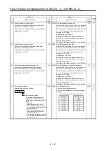
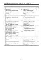
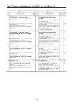
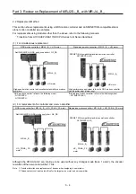
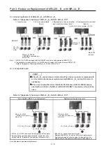
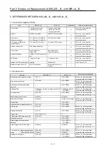
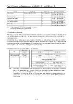
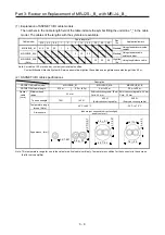
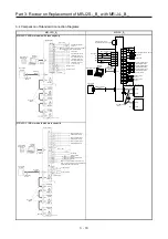
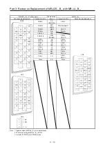
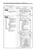
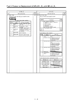
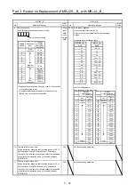
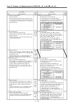
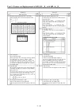
3.4 Comparison of Standard Connection Diagrams
MR-J2S-_B_ MR-J4-_B_
MR-J2S-700B or models with less capacity
20
EM2
2
19
12
DI1
DI3
DI2
Servo amplifier
CN3
FLS
RLS
DOG
Encoder A-phase pulse
(differential line driver)
Encoder B-phase pulse
(differential line driver)
Encoder Z-phase pulse
(differential line driver)
CN3
Electromagnetic brake interlock
13 MBR
9
INP
15 ALM
6
LA
16 LAR
7
LB
17 LBR
8
LZ
18
LZR
Malfunction
In-position
11
LG
Control common
RA1
RA2
RA3
DOCOM
DICOM
3
10
5
DICOM
Main circuit power supply
Personal
computer
CN5
MR Configurator2
+
USB cable
MR-J3USBCBL3M
(option)
24 V DC
Analog monitor 1
Analog monitor 2
MO1
LG
MO2
4
1
14
SD
Plate
2 m or less
CN8
Short-circuit connector
(Packed with the servo amplifier)
10 m or less
10 m or less
Servo amplifier
Forced stop 2
SSCNET III cable
(option)
Servo system
controller
CN1A
CN1B
Cap
CN1A
CN1B
The last servo amplifier
CN1B
CN1A
SSCNET III cable
(option)
24 V DC
DC ± 10 V
DC ± 10 V
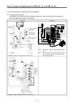
MR-J2S-11KB or models with more capacity
Servo amplifier
Encoder A-phase pulse
(differential line driver)
Encoder B-phase pulse
(differential line driver)
Encoder Z-phase pulse
(differential line driver)
Setup software
(SETUP161E)
Personal
computer
15 m or
lower
10 m or lower
Forced stop
Dynamic brakes
interlock
Electromagnetic brake
interlock
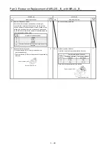
Make sure to connect when using forced stop
(EM1), the electromagnetic brake interlock (MBR),
or the dynamic brake interlock (DB).
Servo system
controller
Bus cable
(Option)
Cable clamp
(Option)
Analog monitor 1
Analog monitor 2
2 m or lower
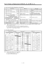
Setting: 0
MR-J2S-B
(2 shafts)
Setting: 1
MR-J2S-B
(3 shafts)
Setting: 2
MR-J2S-B
(n shafts)
Setting: n-1 n = 1 to 8
Bus cable
(Option)
Plate
Servo amplifier
10 m or lower
Setup software
(SETUP161E)
Personal
computer
15 m or
lower
Electromagnetic brake
interlock
Make sure to connect when using forced stop (EM1),
the electromagnetic brake interlock (MBR).
Forced stop
Encoder A-phase pulse
(differential line driver)
Encoder B-phase pulse
(differential line driver)
Encoder Z-phase pulse
(differential line driver)
Control common
Analog monitor 1
Analog monitor 2
2 m or lower
Servo system
controller
Bus cable
(Option)
Cable clamp
(Option)
Setting: 0
MR-J2S-B
(2 shafts)
Setting: 1
MR-J2S-B
(3 shafts)
Setting: 2
MR-J2S-B
(n shafts)
Setting: n-1 n = 1
to
8
Bus cable
(Option)
Plate
Содержание MELSERVO-J2-Super Series
Страница 18: ...Part 1 Summary of MR J2S MR J2M Replacement 1 1 Part 1 Summary of MR J2S MR J2M Replacement ...
Страница 31: ...Part 1 Summary of MR J2S MR J2M Replacement 1 14 MEMO ...
Страница 109: ...Part 3 Review on Replacement of MR J2S _B_ with MR J4 _B_ 3 32 MEMO ...
Страница 161: ...Part 4 Review on Replacement of MR J2S _CP_ CL_ with MR J4 _A_ RJ 4 52 MEMO ...
Страница 219: ...Part 5 Review on Replacement of MR J2S 30 kW or Higher Capacity Models with MR J4 DU_ 5 58 MEMO ...
Страница 220: ...Part 6 Review on Replacement of MR J2M with MR J4 6 1 Part 6 Review on Replacement of MR J2M with MR J4 ...
Страница 239: ...Part 6 Review on Replacement of MR J2M with MR J4 6 20 MEMO ...
Страница 240: ...Part 7 Common Reference Material 7 1 Part 7 Common Reference Material ...
Страница 284: ...Part 7 Common Reference Material 7 45 Click Update Project ...
Страница 342: ...Part 8 Review on Replacement of Motor 8 1 Part 8 Review on Replacement of Motor ...
Страница 409: ...Part 8 Review on Replacement of Motor 8 68 MEMO ...
Страница 461: ...Part 9 Review on Replacement of Optional Peripheral Equipment 9 52 MEMO ...
Страница 462: ...Part 10 Startup Procedure Manual 10 1 Part 10 Startup Procedure Manual ...
Страница 464: ... Appendix 1 Summary of MR J4_B_ RJ020 MR J4 T20 Appendix 1 1 Appendix 1 Summary of MR J4_B_ RJ020 MR J4 T20 ...