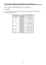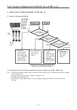
Part 2: Review on Replacement of MR-J2S-_A_ with MR-J4-_A_
2 - 34
MR-J2S-_A_
MR-J4-_A_
Control
mode
No.
Name and function
Initial
value
No.
Name and function
Initial
value
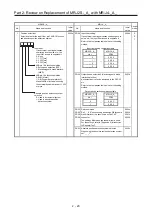
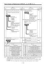
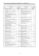
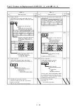
43 Input signal selection 2 (CN1B-5)
When LOP (control switching) is assigned to pin CN1B-5
by [Pr. 42], this parameter cannot be used.
Any input signal can be assigned to pin CN1B-5.
Note that the number of digits of a setting value and the
signals that can be assigned differ depending on the
control mode.
Signals that can be assigned in each control mode are
shown in the table below with abbreviations. Even if other
signals are set, they are ineffective.
Setting
value
(Note) Control mode
P S T
0
1 SON SON SON
2 RES RES RES
3 PC PC
4 TL TL
5 CR CR CR
6 SP1
SP1
7 SP2
SP2
8 ST1
RS2
9 ST2
RS1
A SP3
SP3
B CM1
C CM2
D TL1 TL1 TL1
E CDP CDP CDP
Note. P: Position control mode
S: Speed control mode
T: Torque control mode
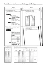
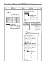
0111h PD03 Input device selection 1L
Any input device can be assigned to pin CN1-15.
(Position control mode and speed control mode)
Set an input device compatible with the MR-J2S-_A_
settings.
For details on input devices, refer to the comparison
table below.
0202h P
S
T
PD04 Input device selection 1H
Any input device can be assigned to pin CN1-15.
(Torque control mode)
Set an input device compatible with the MR-J2S-_A_
settings.
For details on input devices, refer to the comparison
table below.
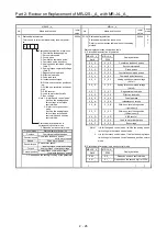
Input device comparison table
MR-J2S-_A_ MR-J4-_A_
Setting
value
Signal
name
Setting
value
Signal
name
1 SON
→
0 2
SON
2 RES
0
3 RES
3 PC
0
4 PC
4 TL
0
5 TL
5 CR
0
6 CR
6 SP1
2
0 SP1
7 SP2
2
1 SP2
8 ST1/RS2
0
7 ST1/RS2
9 ST2/RS1
0
8 ST2/RS1
A SP3
2
2 SP3
B CM1
2
4 CM1
C CM2
2
5 CM2
D TL1
0
9 TL1
E CDP
0
D CDP
0002h
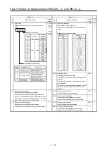
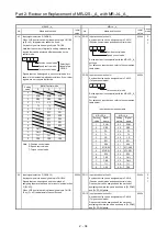
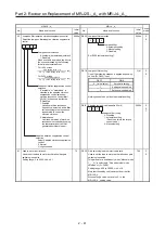
44 Input signal selection 3 (CN1B-14)
Any input signal can be assigned to pin CN1B-14.
Signals that can be assigned and the method of
assigning them are the same as for input signal selection
2 ([Pr. 43]).
When LOP (control switching) is assigned to pin CN1B-
14 by [Pr. 42], this parameter cannot be used.
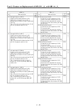
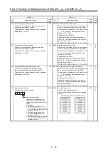
0222h PD11 Input device selection 5L
Any input device can be assigned to pin CN1-19.
(Position control mode and speed control mode)
Devices that can be assigned and the method of
assigning them are the same as shown in [Pr. PD03]
and [Pr. PD04] above.
0303h P
S
T
PD12 Input device selection 5H
Any input device can be assigned to pin CN1-19.
(Torque control mode)
Devices that can be assigned and the method of
assigning them are the same as shown in [Pr. PD03]
and [Pr. PD04] above.
0003h
0
0
Torque control mode
Position control mode
Speed control mode
0
Position control mode
Speed control mode
Torque control mode
Select input
signal of pin
CN1B-5
Содержание MELSERVO-J2-Super Series
Страница 18: ...Part 1 Summary of MR J2S MR J2M Replacement 1 1 Part 1 Summary of MR J2S MR J2M Replacement ...
Страница 31: ...Part 1 Summary of MR J2S MR J2M Replacement 1 14 MEMO ...
Страница 109: ...Part 3 Review on Replacement of MR J2S _B_ with MR J4 _B_ 3 32 MEMO ...
Страница 161: ...Part 4 Review on Replacement of MR J2S _CP_ CL_ with MR J4 _A_ RJ 4 52 MEMO ...
Страница 219: ...Part 5 Review on Replacement of MR J2S 30 kW or Higher Capacity Models with MR J4 DU_ 5 58 MEMO ...
Страница 220: ...Part 6 Review on Replacement of MR J2M with MR J4 6 1 Part 6 Review on Replacement of MR J2M with MR J4 ...
Страница 239: ...Part 6 Review on Replacement of MR J2M with MR J4 6 20 MEMO ...
Страница 240: ...Part 7 Common Reference Material 7 1 Part 7 Common Reference Material ...
Страница 284: ...Part 7 Common Reference Material 7 45 Click Update Project ...
Страница 342: ...Part 8 Review on Replacement of Motor 8 1 Part 8 Review on Replacement of Motor ...
Страница 409: ...Part 8 Review on Replacement of Motor 8 68 MEMO ...
Страница 461: ...Part 9 Review on Replacement of Optional Peripheral Equipment 9 52 MEMO ...
Страница 462: ...Part 10 Startup Procedure Manual 10 1 Part 10 Startup Procedure Manual ...
Страница 464: ... Appendix 1 Summary of MR J4_B_ RJ020 MR J4 T20 Appendix 1 1 Appendix 1 Summary of MR J4_B_ RJ020 MR J4 T20 ...

