


Part 2: Review on Replacement of MR-J2S-_A_ with MR-J4-_A_
2 - 31
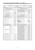
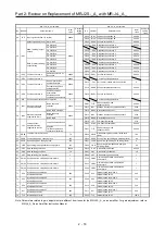
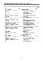
MR-J2S-_A_
MR-J4-_A_
Control
mode
No.
Name and function
Initial
value
No.
Name and function
Initial
value
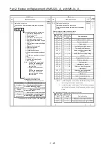
29 Analog speed command offset
Used to set the offset voltage of VC (Analog speed
command).
For example, if switching on ST1 (forward rotation start)
with 0 V applied to VC causes CCW rotation, set a
negative value.
When VC automatic offset is used, the automatically
offset value is set to this parameter.
The initial value is provided before shipment by the VC
automatic offset function on condition that the voltage
between VC and LG is 0 V.
Setting range: -999 to 999 mV
Differs
depending
on the
servo
amplifier.
PC37 Analog speed command offset
Used to set the offset voltage of VC (Analog speed
command).
The initial value is provided before shipment by the
VC automatic offset function on condition that the
voltage between VC and LG is 0 V.
For example, when the motor rotates by switching
on ST1 (forward rotation start) with 0 V applied to
VC, set an offset voltage.
Setting range: -9999 to 9999 mV
Differs
depending
on the
servo
amplifier.
S
Analog speed limit offset
Used to set the offset voltage of VLA (Analog speed
limit).
For example, if switching on RS1 (forward rotation
selection) with 0 V applied to VLA causes CCW rotation,
set a negative value.
When VC automatic offset is used, the automatically
offset value is set to this parameter.
The initial value is provided before shipment by the VC
automatic offset function on condition that the voltage
between VLA and LG is 0 V.
Setting range: -999 to 999 mV
Analog speed limit offset
Used to set the offset voltage of VLA (Analog speed
limit).
The initial value is provided before shipment by the
VC automatic offset function on condition that the
voltage between VC and LG is 0 V.
When the motor rotates by switching on RS1
(Forward rotation selection) with 0 V applied to VLA,
set an offset voltage.
Setting range: -9999 to 9999 mV
T
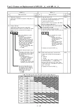
30 Analog torque command offset
Used to set the offset voltage of TC (Analog torque
command).
Setting range: -999 to 999 mV
0
PC38 Analog torque command offset
Used to set the offset voltage of TC (Analog torque
command).
Setting range: -9999 to 9999 mV
0
T
Analog torque limit offset
Used to set the offset voltage of TLA (Analog torque
limit).
Setting range: -999 to 999 mV
Analog torque limit offset
Used to set the offset voltage of TLA (Analog torque
limit).
Setting range: -9999 to 9999 mV
S
31 Analog monitor 1 offset
Used to set the offset voltage of Analog monitor 1 (MO1).
Setting range: -999 to 999 mV
0
PC39 Analog monitor 1 offset
Used to set the offset voltage of MO1 (Analog
monitor 1).
Setting range: -9999 to 9999 mV
0 P
S
T
32 Analog monitor 2 offset
Used to set the offset voltage of Analog monitor 2 (MO2).
Setting range: -999 to 999 mV
0
PC40 Analog monitor 2 offset
Used to set the offset voltage of MO2 (Analog
monitor 2).
Setting range: -9999 to 9999 mV
0 P
S
T
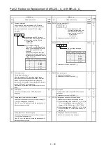
33 Electromagnetic brake sequence output
Used to set the delay time (Tb) between MBR
(Electromagnetic brake interlock) OFF and base circuit
shut-off.
Setting range: 0 to 1000 ms
100
PC16 Electromagnetic brake sequence output
Used to set the delay time (Tb) between MBR
(Electromagnetic brake interlock) OFF and base
circuit shut-off.
Setting range: 0 to 1000 ms
Set the same value as for MR-J2S-_A_.
0 P
S
T
34 Load to motor inertia ratio
Used to set the motor inertia ratio to the servo motor
shaft inertia moment.
When auto tuning mode 1 or interpolation mode is
selected, the result of auto tuning is automatically used.
In this case, the value varies between 0 and 1000.
Setting range: 0 to 3000; Unit: x0.1
70
PB06 Load to motor inertia ratio
When auto tuning mode 1 is selected, the auto
tuning result is automatically used.
Setting range: 0.00 to 300.00; Unit: x1.0
Note that the setting unit is different from that for
MR-J2S-_A_.
When setting a value manually, set a value 0.1 x the
MR-J2S-_A_ setting value.
7.00 P
S
Содержание MELSERVO-J2-Super Series
Страница 18: ...Part 1 Summary of MR J2S MR J2M Replacement 1 1 Part 1 Summary of MR J2S MR J2M Replacement ...
Страница 31: ...Part 1 Summary of MR J2S MR J2M Replacement 1 14 MEMO ...
Страница 109: ...Part 3 Review on Replacement of MR J2S _B_ with MR J4 _B_ 3 32 MEMO ...
Страница 161: ...Part 4 Review on Replacement of MR J2S _CP_ CL_ with MR J4 _A_ RJ 4 52 MEMO ...
Страница 219: ...Part 5 Review on Replacement of MR J2S 30 kW or Higher Capacity Models with MR J4 DU_ 5 58 MEMO ...
Страница 220: ...Part 6 Review on Replacement of MR J2M with MR J4 6 1 Part 6 Review on Replacement of MR J2M with MR J4 ...
Страница 239: ...Part 6 Review on Replacement of MR J2M with MR J4 6 20 MEMO ...
Страница 240: ...Part 7 Common Reference Material 7 1 Part 7 Common Reference Material ...
Страница 284: ...Part 7 Common Reference Material 7 45 Click Update Project ...
Страница 342: ...Part 8 Review on Replacement of Motor 8 1 Part 8 Review on Replacement of Motor ...
Страница 409: ...Part 8 Review on Replacement of Motor 8 68 MEMO ...
Страница 461: ...Part 9 Review on Replacement of Optional Peripheral Equipment 9 52 MEMO ...
Страница 462: ...Part 10 Startup Procedure Manual 10 1 Part 10 Startup Procedure Manual ...
Страница 464: ... Appendix 1 Summary of MR J4_B_ RJ020 MR J4 T20 Appendix 1 1 Appendix 1 Summary of MR J4_B_ RJ020 MR J4 T20 ...