59 38 399 D3352
6 – 44
D3352.076.01.13.02
07.2008
6.16 Replacing the PAN (TSA) sensor holder
Tabs 6
5.
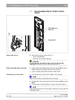
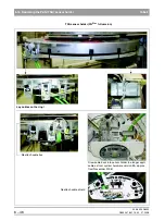
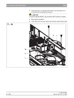
Detach the shield clamp (L13) on the rear side of the
connection socket.
6.
Loosen the connector screw connection on the front side of the connec-
tion socket and thread the connector to the rear through the connection
socket and the sensor holder.
Installing the new sensor holder
7.
Install the new sensor holder in the reverse order of removal.
NOTE
i
Don't forget to plug all connectors and cables back in again in their original
position and reattach the cable shields as well as all cable ties and strain re-
liefs (see section "Laying cables when replacing the PAN sensor holder" on
page 6-45).
ATTENTION: What to do after replacement?
– Perform the PAN system adjustment (see section 4.3).
The TSA adjustment also must be performed for TSA units!
– Take diaphragm test exposures for possible later
evaluation by an expert.
Shield clamp
6.
5.
Summary of Contents for ORTHOPHOS XG 3 DS
Page 4: ......
Page 9: ...ORTHOPHOS XG 1General information...
Page 12: ...59 38 399 D3352 1 4 D3352 076 01 13 02 07 2008 Tab1...
Page 59: ...ORTHOPHOS XG 2 Messages...
Page 124: ...59 38 399 D3352 2 66 D3352 076 01 13 02 07 2008 2 6 List of available service routines Tab 2...
Page 125: ...ORTHOPHOS XG 3 Troubleshooting...
Page 153: ...ORTHOPHOS XG 4 Adjustment...
Page 269: ...ORTHOPHOS XG 5 Service routines...
Page 433: ...ORTHOPHOS XG 6 Repair...
Page 436: ...59 38 399 D3352 6 4 D3352 076 01 13 02 07 2008 Tab6...
Page 530: ...59 38 399 D3352 6 98 D3352 076 01 13 02 07 2008 6 21 Replacing cables Tabs 6...
Page 531: ...ORTHOPHOS XG 7 Maintenance...
Page 577: ...b 59 38 399 D3352 D3352 076 01 13 02 07 2008...

