


båÖäáëÜ
59 38 399 D3352
D3352.076.01.13.02
07.2008
4 – 87
Tab 4 4.4 Adjusting the cephalometer (XG
Plus
/ XG 5, if ceph is installed)
4.
4
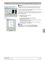
Evaluating the X-ray image
7.
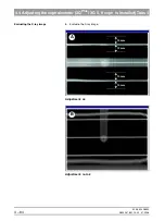
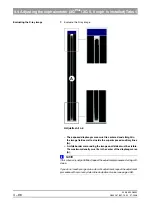
Evaluate the X-ray image:
– A horizontal bar must be visible in the center of the image (A). If
this bar is visible, the exposure is OK and ...
– the two beams imaged are within the tolerance band of
± 10 mm (A).
NOTE
i
If this criterion is not yet fulfilled, repeat the adjustment procedure starting with
step 5.
If you do not reach your goal via automatic adjustment, repeat the adjustment
procedure with a manually determined adjustment value (see page 4-88).
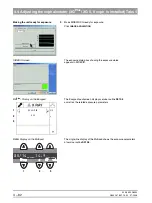
Saving a value
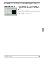
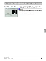
8.
If the image is identical to the ideal image
(A)
, save the value:
Click
SAVE
VALUES
z
Go on to the next adjustment step.
Adjustment: ok
A
Summary of Contents for ORTHOPHOS XG 3 DS
Page 4: ......
Page 9: ...ORTHOPHOS XG 1General information...
Page 12: ...59 38 399 D3352 1 4 D3352 076 01 13 02 07 2008 Tab1...
Page 59: ...ORTHOPHOS XG 2 Messages...
Page 124: ...59 38 399 D3352 2 66 D3352 076 01 13 02 07 2008 2 6 List of available service routines Tab 2...
Page 125: ...ORTHOPHOS XG 3 Troubleshooting...
Page 153: ...ORTHOPHOS XG 4 Adjustment...
Page 269: ...ORTHOPHOS XG 5 Service routines...
Page 433: ...ORTHOPHOS XG 6 Repair...
Page 436: ...59 38 399 D3352 6 4 D3352 076 01 13 02 07 2008 Tab6...
Page 530: ...59 38 399 D3352 6 98 D3352 076 01 13 02 07 2008 6 21 Replacing cables Tabs 6...
Page 531: ...ORTHOPHOS XG 7 Maintenance...
Page 577: ...b 59 38 399 D3352 D3352 076 01 13 02 07 2008...