background image

båÖäáëÜ

59 38 399 D3352
D3352.076.01.13.02

07.2008

6 – 97

Tab 6

6.21 Replacing cables

6.21

6.21.3

Laying cable L1 and the grounding strap
(in cable track 1)

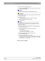
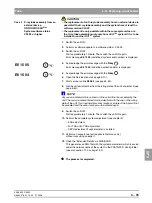
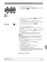
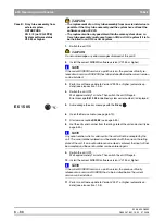
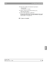
The procedure for replacing cable L1 and the grounding strap is basically 
analogous to the procedure described in chapter 6.21.2.

Summary of Contents for ORTHOPHOS XG 3 DS

Page 1: ...b loqelmelp udm ap L loqelmelp ud R ap L loqelmelp ud P ap p j s NPKM ORTHOPHOS XGPlus DS Easypad ORTHOPHOS XG 5 3 3 PPE DS T R Prog S kV mA P1 Multipad...

Page 2: ...require Spare parts list Order No 59 38 423 ORTHOPHOS XGPlus DS Ceph ORTHOPHOS XG 5 DS Ceph ORTHOPHOS XG 3 DS Wiring diagrams Order No 59 38 332 ORTHOPHOS XGPlus DS Ceph ORTHOPHOS XG 5 DS Ceph ORTHOPH...

Page 3: ...General information Software update 1 Messages 2 Troubleshooting 3 Adjustment 4 Service routines 5 Repair 6 Maintenance 7...

Page 4: ......

Page 5: ...view 1 38 1 13 Illustrations of boards 1 42 1 14 Removing the covers 1 50 2 Messages 2 3 2 1 Help messages 2 4 2 2 System messages 2 6 2 3 Status displays 2 6 2 4 Error messages 2 6 2 5 List of error...

Page 6: ...Selecting a service routine 5 15 5 3 Service routines with SIDEXIS 5 18 5 4 Service routine S001 5 21 5 5 Service routine S002 5 23 5 6 Service routine S005 5 28 5 7 Service routine S007 5 40 5 8 Serv...

Page 7: ...laser module PAN 6 28 6 9 Replacing adjusting the FH light localizer Ceph 6 30 6 10 Removing the light localizers from the ring for the XGPlus and XG 5 if present 6 32 6 11 Replacing the support piece...

Page 8: ...the support piece bite block holder 7 9 7 5 Checking the light localizers 7 10 7 6 Checking the X ray images 7 12 7 7 Checking the tube data 7 13 7 8 Checking the diaphragm 7 17 7 9 Checking the cable...

Page 9: ...ORTHOPHOS XG 1General information...

Page 10: ...11 1 6 Demo mode Operation without radiation release1 13 1 6 1 Switching the demo mode ON 1 14 1 6 2 Switching the demo mode OFF 1 14 1 7 Demo mode Repacking and transport 1 15 1 8 List of software ve...

Page 11: ...eter arm mounted on left side or on right side 1 37 1 11 4 Remote control 1 37 1 12 Cabling overview 1 38 1 13 Illustrations of boards 1 42 1 13 1 Boards in the slide 1 42 1 13 2 Boards in the stand 1...

Page 12: ...59 38 399 D3352 1 4 D3352 076 01 13 02 07 2008 Tab1...

Page 13: ...n con tained in this Service Manual All such information is highlighted by one of three signal words i e CAUTION WARNING or DANGER CAUTION Nonobservance may result in minor physical injuries or materi...

Page 14: ...XG 3 3 PPE system ver sion is not possible with a cephalometer NOTE i The version with the ceph arm mounted on the left side is basically described and illustrated in this Service Manual Unless descri...

Page 15: ...ersions T R Prog S kV mA T R Prog S kV mA T R Prog S kV mA ORTHOPHOS XGPlus with ceph arm on right side with ceph arm on left side Comfort class Easypad basic or full version TSA option remote control...

Page 16: ...odontic image series P 1 C 3 C 4 without cooling periods z No TSA configuration level z No TSA operation possible z No welcome screen 1 3 2 XG 3 system version 5 panoramic programs z P 1 P 1C z P 1L P...

Page 17: ...2 z S 1 z MS 1 5 Ceph programs z C 1 C 2 C 3 C 3F C 4 Functions z Half views of right left side possible only with P1 not upper lower jaw z Preselection of individual quadrants not possible z Constant...

Page 18: ...ew and individual quadrants P 1A P 2 A C P 10 A C P12 z Selectable upper lower jaw partial view and individual quadrants P 1 A C P 2 A C P 10 A C z Temporomandibular joint views TM 2 TM 3 TM 4 TM 5 TM...

Page 19: ...Easypad XGPlus Cooling period The cooling period between two exposures is maintained by an automatic exposure blocking function according to the pulse pause ratio A countdown of the waiting time is di...

Page 20: ...es with radiation must be taken to check a measurement make sure that the prescribed cool down intervals are observed They are maintained by an automatic exposure blocking function see operating instr...

Page 21: ...Operation without radiation release 1 6 1 6 Demo mode Operation without radiation release NOTE i Starting with system SW version V02 28 the complete possible functionality of the system class is simu...

Page 22: ...g procedure in reverse order 1 6 2 Switching the demo mode OFF z Switch the unit OFF 1 Remove the cover of the tube assembly 2 Loosen screws A and remove cover plate B 3 Set dip switch S2 DX6 to posit...

Page 23: ...or Easypad XGPlus Bottom edge of slide cover 702 mm NOTE i The bottom edge of the slide cover must be at the same height as the mark ings A in the column Cephalometer z Start service routine S034 test...

Page 24: ...02 60 02 34 02 42 02 33 compatible with SIDEXIS versions V01 61 and higher Overall software V 02 32 02 60 02 34 02 43 02 33 compatible with SIDEXIS versions V01 61 and higher Remote control Remarks B...

Page 25: ...02 33 compatible with SIDEXIS versions V01 53 and higher Overall software V 02 32 02 60 02 34 02 43 02 23 02 33 compatible with SIDEXIS versions V01 53 and higher Remote control Remarks Board DX42 Ove...

Page 26: ...s V01 53 and higher Overall software V 02 28 02 60 02 33 02 40 02 23 02 33 02 33 02 42 compatible with SIDEXIS versions V01 53 and higher Overall software V 02 28 2 02 60 02 33 02 40 01 02 23 02 34 02...

Page 27: ...oftware Version V02 20 or higher V 01 51 requires ORTHOPHOS XG 5 Overall Software Version V02 20 or higher V 01 53 requires ORTHOPHOS XG 5 Overall Software Version V02 20 or higher V 01 54 requires OR...

Page 28: ...33 02 32 02 42 compatible with SIDEXIS versions V01 53 and higher Overall software V 02 28 02 60 02 44 02 40 02 23 02 33 02 33 02 42 compatible with SIDEXIS versions V01 53 and higher Overall software...

Page 29: ...are Version V02 20 or higher V 01 51 requires ORTHOPHOS XGPlus Overall Software Version V02 20 or higher V 01 53 requires ORTHOPHOS XGPlus Overall Software Version V02 20 or higher V 01 54 requires OR...

Page 30: ...A operation For downgrading from a software version V2 20 to one V2 20 with the TSA mode activated the TSA sensor holder must be equipped with the transport safety device and set to the PAN position C...

Page 31: ...re version permissible for each sys tem class CAUTION If an update is nevertheless performed accidentally the version must be downgraded again immediately before acknowledging any error messages or ex...

Page 32: ...he ATTRIBUTES tab and then SOFTWARE UPDATE The dialog box for entering the service password appears on the screen Entering the password 3 Enter the service password NOTE i As servicepassword enter the...

Page 33: ...Product Info X ray Systems www sirona com Selecting the update mode 6 Select the mode for the software update You can select two different update modes via the index tabs z Automatic The software of a...

Page 34: ...Modules which are not elements of the current system configuration e g DX71 with XGPlus or as a removable medium e g sensors are not connected are marked by a broken red bar If the actual status of th...

Page 35: ...or Ceph must be inserted in the cor responding slots Exposure readiness must be deselected in SIDEXIS and the system must not be in the service mode already The update is started A message box informs...

Page 36: ...5 48 Program version included NOTE i Modules which are connected and whose program status agrees with that of the current main program version are marked by a continuous green bar Modules which are no...

Page 37: ...update 1 Switch the unit ON 2 Execute the software update to Version V02 30 or higher automatic up date as described on page 1 24 3 Switch the unit OFF Wait for approx 1 minute Then switch the unit ON...

Page 38: ...04 undefined activation data is displayed 4 Acknowledge the error message with the R key 5 Open the Service menu see page 5 10 6 Start service routine S008 3 and confirm the unit serial number see pag...

Page 39: ...the future as well plug them into the slots on the panoramic unit and or cephalometer before you begin the update 1 Switch the unit ON 2 Execute the software update to Version V02 30 or higher automa...

Page 40: ...ll down menus PROGRAMS SIDEXIS CONFIGURATION OF X RAY COMPONENTS Opening the EXTENDED DETAILS menu 2 Open the EXTENDED DETAILS menu Click the ATTRIBUTES tab and then EXTENDED DETAILS The current param...

Page 41: ...configured in S17 9 actual value mounted 01 Setting of image format configured in S17 11 actual value enabled 01 Settings of welcome screen configuration configured in S17 14 actual value 01 1 02 1 0...

Page 42: ...nd components The X ray system comprises the following main modules z Slide with rotary unit z Stand z Cephalometer arm on right side or on left side optional z Remote control optional Cephalometer ar...

Page 43: ...us Multipad XG 5 3 3 PPE Component Designation Function Boards DX1 Open loop automatic control in general DX11 Controller board DX5 Headrest adapter DX6 Open loop automatic control for tube assembly D...

Page 44: ...from November 2006 new systems will be delivered with the new version of board DX32 see Section 1 9 As of hardware version BA from November 2006 new systems will be delivered without board DX41 DX41 D...

Page 45: ...arm mounted on left side or on right side 1 11 4 Remote control DX91 M S LS Component Designation Function Boards DX91 Cephalometer control Motors M S Stepping motors linear movement of secondary dia...

Page 46: ...DX6 J6 1 2 3 4 5 4 DX1 DX6 5 3 1 2 Line filter DX32 Power switch Wago terminal DX1 J306 J302 DX6 J2 J3 DX1 J901 DX41 DX1 X303 DX41 X100 DX1 X104 DX7 X102 DX1 X302 DX7 X103 DX1 X102 DX61 X501 6 7 8 9...

Page 47: ...12 b 59 38 399 D3352 D3352 076 01 13 02 07 2008 1 39 Tab 1 1 12 Cabling overview 1 12 DX1 X306 DX61 X101 DX1 X404 DX5 X1 DX1 X610 DX1 X403 18 DX5 DX61 12 DX1 DX81 M HA LS sensor 13 19 16 12 13 16 18 1...

Page 48: ...DX41 DX42 DX81 35 22 24 21 21 31 Potentiometer DX91 M U LS Sensor DX42 X100 DX41 X103 DX61 DX91 DX5 DX41 Media Konverter DX81 X100 DX1 X503 17 17 117 21 22 23 25 31 35 38 Unit HW version BA and higher...

Page 49: ...1 12 b 59 38 399 D3352 D3352 076 01 13 02 07 2008 1 41 Tab 1 1 12 Cabling overview 1 12 DX91 36 39 DX1 40 37 DX91 X6 DX91 X101 DX1 X103 DX1 X309 36 37 39 40...

Page 50: ...he slide Boards DX1 DX11 To facilitate cable routing to the side RJ 45 connectors with a 45 incline were introduced in August 2006 Board DX5 DX1 DX11 X500 X307 X503 X303 X104 X403 X611 X607 X306 X302...

Page 51: ...02 07 2008 1 43 Tab 1 1 13 Illustrations of boards 1 13 Board DX6 not available as spare part Board DX61 not for XG 3 3 PPE X2 X1 X306 X305 J2 J3 J6 S2 X3 F201 X501 X101 X203 X202 X406 X405 X402 X401...

Page 52: ...s repair part NOTE i Board DX7 is shown here only for enhanced clarity The Easypad may be replaced only as a complete unit Board DX7 XG 5 3 3 PPE only not available as repair part NOTE i Board DX71 is...

Page 53: ...1 1 13 Illustrations of boards 1 13 Boards DX81P DX85P not available as repair parts NOTE i Boards DX81 and DX85 are shown here only for enhanced clarity CAUTION It is not allowed to open the sensor T...

Page 54: ...3 02 07 2008 1 13 Illustrations of boards Tab 1 1 13 2 Boards in the stand Board DX32 up to unit hardware version AG Board DX32 as of unit hardware version BA from November 2006 X100 F100 X1 F101 F102...

Page 55: ...1 13 Illustrations of boards 1 13 Board DX41 omitted as of unit hardware version BA from November 2006 1 13 3 Boards in the cephalometer arm mounted on right side or on left side Board DX91 X100 X103...

Page 56: ...38 399 D3352 1 48 D3352 076 01 13 02 07 2008 1 13 Illustrations of boards Tab 1 1 13 4 Boards in the remote control Board DX42 up to unit hardware version AG X200 X201 X107 X101 X100 X105 V103 V100 V1...

Page 57: ...8 399 D3352 D3352 076 01 13 02 07 2008 1 49 Tab 1 1 13 Illustrations of boards 1 13 Board DX42 as of unit hardware version BA from November 2006 X200 X201 X107 X101 X108 X105 Jumper X109 und X110 V100...

Page 58: ...11 10 5 14 1 Profile cover 2 Intermediate piece 3 Arm cover top 4 Slide cover top rear 5 Slide cover bottom rear 6 Support cover top 7 Support cover bottom 8 Tube assembly cover front 9 Tube assembly...

Page 59: ...ORTHOPHOS XG 2 Messages...

Page 60: ...Help messages 2 3 2 2 System messages 2 6 2 3 Status displays 2 6 2 4 Error messages 2 6 2 4 1 Ex yy zz 2 7 2 4 2 Ex yy zz 2 8 2 4 3 Ex yy zz 2 8 2 4 4 General handling of error messages 2 8 2 5 List...

Page 61: ...of the remote control There are 3 groups of message texts z Help messages Hxxx Help messages are caused by operator errors The user must take action z Error messages Exyyzz Error messages indicate sy...

Page 62: ...ia Easypad H3 30 XG 3 PPE only Indicates number of exposures remaining PPE concept 1 After each switch on see S017 22 2 After each exposure if the number of expo sures remaining is below the defined w...

Page 63: ...r proceed as de scribed in section 2 5 H4 07 Unit supports default settings for this exposure since the settings specified by SIDEXIS cannot be taken over z Perform alternative program setting H4 10 T...

Page 64: ...able on page 2 7 System code Description Actions required S100 ORTHOPHOS XG is started z Wait no action required S110 Exposure cannot be performed z Quit readiness for exposure switch unit OFF wait fo...

Page 65: ...escribed in section 2 5 4 Malfunction or mechanicalobstruction of unit movements This error group includes all errors that indi cate problems with the motor controlled movements on the outside of the...

Page 66: ...ion 2 5 and take appropriate action to eliminate the corresponding error or fault In some cases it may make sense to obtain more information on the history and frequency of errors via the error loggin...

Page 67: ...It appears only after you acknowledge the first error message z Checking the CAN bus 3 6 z Please contact the Sirona Customer Service Center CSC to find out whether a bugfix by means of a software up...

Page 68: ...a bugfix by means of a software update is possible and per form such an update if necessary 1 22 z Replace the X ray tube assembly 6 38 E7 06 10 Module is stuck in bootloader stage z Check board DX6...

Page 69: ...3 6 z Please contact the Sirona Customer Service Center CSC to find out whether a bugfix by means of a software update is possible and per form such an update if necessary 1 22 E5 06 32 Minimum prehe...

Page 70: ...m service routines S005 2 5 29 z Replace the X ray tube assembly 6 38 E6 06 52 MAmax z Perform service routines S005 2 5 29 z Replace the X ray tube assembly 6 38 E6 06 53 KVmax Perform service routin...

Page 71: ...It appears only after you acknowledge the first error message z Checking the CAN bus 3 6 z Please contact the Sirona Customer Service Center CSC to find out whether a bugfix by means of a software up...

Page 72: ...48 perform a software update if necessary 1 22 z Check user interface with electronics DX7 or 6 59 Replace Easypad 6 21 z Please contact the Sirona Customer Service Center CSC to find out whether a bu...

Page 73: ...Check user interface with electronics DX7 or Replace Easypad 6 59 6 21 E3 07 31 Forehead support key pressed during power on E3 07 32 Temple support keys actuated during power on E3 07 33 Light locali...

Page 74: ...lace board DX1 6 59 E1 10 03 The flash file system must be format ted Note Occurs after replacement of board DX11 z Acknowledge error HINWEIS i The flash file system is formatted and error message E1_...

Page 75: ...Implausible data in EEPROM z Check the device configuration via service rou tines S017 and S018 and reconfigure if neces sary 5 77 5 109 z Check adjustment with diaphragm test expo sures 7 17 If the...

Page 76: ...ck software versions via info screen or ser vice routine S008 2 5 48 perform a software update if necessary 1 22 If the error occurs again z Perform a software update bug fix 1 22 E6 11 13 Up to HW ve...

Page 77: ...If the user mode is expressly required z Switch the demo mode OFF VORSICHT Radiation can be released after the demo mode is switched off 1 13 Error code Description Actions required see page Error cod...

Page 78: ...tion and run a test cycle via P1 If the error occurs again z Check light barrier V1_1 X802 with service routine S015 5 5 74 replace light barrier if necessary 6 49 z Check electric drive and jolt free...

Page 79: ...ctuator 2 has not reached pan home position z Check the actuator mechanisms manually for smooth and easy running In case of stiffness z manually reset the actuators to the zero position and run a test...

Page 80: ...place light barrier if necessary 6 49 z Check electric drive and jolt free running with service routine S015 5 free travel 5 74 z replace the actuators and or spindles and 6 17 replace board DX1 if ne...

Page 81: ...6 59 E4 13 24 Ring motor position counter error z Check the actuator mechanisms manually for smooth and easy running reset actuators to zero position of necessary z Check the ring drive mechanism manu...

Page 82: ...restart Switch the unit OFF Wait 30 sec Switch unit ON z Repeat procedure and observe causal error messages E6 13 28 Error when activating ring motor z Unit restart Switch the unit OFF Wait 30 sec Sw...

Page 83: ...g correct or replace the limit switch if necessary E5 13 33 Height adjustment motor position counter too small for current position Note Error may occur after replacement of board DX11 z Run HA motor...

Page 84: ...eight adjustment motor is not ready for operation This error is a sequential fault z Unit restart Switch the unit OFF Wait 30 sec Switch unit ON z Repeat procedure and observe causal error messages E6...

Page 85: ...E5 13 43 The door was opened during the exposure z Check the X ray signal path 3 18 E5 13 50 Forehead support has not left home position despite movement pulses z Check light barriers V5_1 to V5_4 3 1...

Page 86: ...ics replace if necessary 6 19 z Replace board DX1 6 59 E6 13 58 Error when activating forehead sup port motor Timeout of FPGA module on board DX1 z Acknowledge error If the error occurs again z Replac...

Page 87: ...c Switch unit ON and check functioning z Please contact the Sirona Customer Service Center CSC to find out whether a bugfix by means of a software update is possible and per form such an update if nec...

Page 88: ...whether a bugfix by means of a software update is possible and per form such an update if necessary 1 22 If the error occurs repeatedly z Replace board DX1 6 59 E6 13 87 Error when activating pulse g...

Page 89: ...wledge error and quit service domain from unit and SIDEXIS end z Switch unit OFF and ON again and reselect SI DEXIS If the error occurs again z Perform network diagnosis in coordination with the Siron...

Page 90: ...eck for kinks and connectors repair or replace if necessary Check board DX1 replace if necessary Perform service routine S032 10 In this way it can be determined whether the fault is stationary or per...

Page 91: ...04 Product activation keys invalid or not available Note Occurs after replacement of tube assembly DX6 or DX11 and possibly after software updates See also chapter Measures following replacement of bo...

Page 92: ...sal error message It appears only after you acknowledge the first error message z Checking the CAN bus 3 6 z Please contact the Sirona Customer Service Center CSC to find out whether a bugfix by means...

Page 93: ...s 3 6 z Check software versions via info screen or ser vice routine S008 2 5 48 perform a software update if necessary 1 22 z Replace board DX41 6 59 z Please contact the Sirona Customer Service Cente...

Page 94: ...board DX42 3 12 replace if necessary 6 59 z Check board DX41 3 12 replace if necessary 6 59 E6 41 23 Hardware fault at controller input on board DX41 Board DX41 detects a wrong signal level of the har...

Page 95: ...acknowledge the first error message z Check software version of DX42 in comparison to overall software version via service routine S008 2 5 48 perform a software update if necessary 1 22 z Checking t...

Page 96: ...oftware of boards is incom patible z Check software versions via info screen or ser vice routine S008 2 5 48 perform a software update if necessary 1 22 z Checking the CAN bus 3 6 z Replace board DX42...

Page 97: ...does not start Note Occurs after power on in the start screen z Check configuration with or without DX41 via service routine S017 9 5 91 configure correctly if necessary 5 91 z Check the signal path...

Page 98: ...Trigger Protocol E3 42 31 Release button actuated during power on The hardware signal for radiation release is applied on board DX42 when the unit is switched on z see section entitled Error analysis...

Page 99: ...on with other causal error messages Please also observe the causal error message It appears only after you acknowledge the first error message If the error occurs during the acceptance constancy test...

Page 100: ...e z Checking the CAN bus 3 6 z Check power supply of board DX11 measuring point 3 3 V on board DX1 see wiring diagrams If 3 3 V are present replace board DX11 6 59 If 3 3 V are not present replace boa...

Page 101: ...DX61 replace if necessary 3 12 Replace board DX61 or 6 59 Replace diaphragm unit 6 34 E5 61 21 Horizontal motor limit switch error z Check light barrier V61_1 and connectors re place if necessary 3 1...

Page 102: ...hragm unit 6 34 E5 61 40 Filter motor malfunction during opera tion z Allow unit to cool down If the error occurs again z Check board DX61 replace if necessary 3 12 Replace board DX61 or 6 59 Replace...

Page 103: ...ce sensor holder if necessary 6 43 z Check board DX61 replace if necessary 3 12 Replace board DX61 or 6 59 Replace diaphragm unit 6 34 E5 61 52 Sensor positioning drive movement error z Acknowledge er...

Page 104: ...accord ing to wiring diagrams replace diaphragm unit if necessary 6 34 z Check cable L11 3 17 replace if necessary 6 91 z Check voltage path from DX32 to DX1 X102 according to wiring diagrams replace...

Page 105: ...c tion with other causal error messages Please also observe the causal error message It appears only after you acknowledge the first error message z Checking the CAN bus 3 6 z Please contact the Siron...

Page 106: ...bus 3 6 z Check software versions via info screen or ser vice routine S008 2 5 48 perform a software update if necessary 1 22 z Check board DX71 or 3 59 z replace Multipad 6 21 z Please contact the S...

Page 107: ...ON making sure that the Multipad is not actuated during boot up If the error occurs again z Replace board DX71 or Multipad 6 59 6 21 E3 71 31 Forehead support key pressed during power on E3 71 32 Tem...

Page 108: ...h other causal error messages Please also observe the causal error message It appears only after you acknowledge the first error message z Checking the CAN bus 3 6 z If the error is a software error k...

Page 109: ...the CAN bus 3 6 z Check software versions via info screen or ser vice routine S008 2 5 48 perform a software update if necessary 1 22 z Check pan sensor replace if necessary z Please contact the Siron...

Page 110: ...eplacement sen sor replace sensor if necessary z Check connector X500 on DX1 replace DX1 or DX11 if necessary 6 59 z Replace board DX1 or DX11 6 59 E5 81 24 PAN Sensor in PAN slot not detected z Check...

Page 111: ...e z Acknowledge error and repeat procedure If the error occurs again z Perform a software update 1 22 z Check version compatibility of XG software and Sidexis 1 16 perform a software update if necessa...

Page 112: ...essages Please also observe the causal error message It appears only after you acknowledge the first error message z Checking the CAN bus 3 6 z Please contact the Sirona Customer Service Center CSC to...

Page 113: ...z Check software versions via info screen or service routine S008 2 5 48 perform a software update if necessary 1 22 z Check ceph sensor replace if necessary z Please contact the Sirona Customer Serv...

Page 114: ...e error occurs again z Check ceph sensor replace if necessary E5 81 77 Ceph Voltage error detected on sensor CCD voltages on board DX81P Note If this error occurs in connection with other causal error...

Page 115: ...r messages Please also observe the causal error message It appears only after you acknowledge the first error message z Checking the CAN bus 3 6 z Please contact the Sirona Customer Service Center CSC...

Page 116: ...form a software update if necessary 1 22 z Replace board DX91 6 59 z Please contact the Sirona Customer Service Center CSC to find out whether a bugfix by means of a software update is possible and pe...

Page 117: ...whether a bugfix by means of a software update is possible and per form such an update if necessary 1 22 E5 91 22 Sensor drive timeout z Check motor M91_3 incl cable and connector replace if necessary...

Page 118: ...59 E6 91 42 Nose support pot compensation not yet performed z Perform software update to version V02 25 or higher 1 22 If the error occurs again z Replace DX91 6 59 E1 91 50 Voltage error on DX91 40V...

Page 119: ...be voltage mea surement reproducibility measurement equiv alent dose measurement 5 23 S005 General X ray tube assembly service Test step 2 Automatic alignment of preheating board DX6 with display of s...

Page 120: ...ster of mod ules z on suspicion of unstable CAN bus z in case of accumulated error messages EX yy 12 Ex yy 06 Ex yy 07 Ex yy 03 z not suitable as an accompanying measure e g check connector of CAN bus...

Page 121: ...of board DX11 or the headrest Test step 11 for XG 5 only Select image format z for changing the configuration Test step 12 V02 22 or higher XGPlus only Activate deactivate the preview image z At the c...

Page 122: ...switch pulse counter Test step 5 V02 27 and higher Limit minimum travel height Test step 6 V02 27 and higher Undo limit of minimum travel height setting z if the minimum travel height must be limited...

Page 123: ...ter Test step 7 for XGPlus only Set the ring type z for PAN units up to serial number 20056 for PAN CEPH units up to serial number 40104 Test step 8 User specific definition of shadowing limit for C1...

Page 124: ...59 38 399 D3352 2 66 D3352 076 01 13 02 07 2008 2 6 List of available service routines Tab 2...

Page 125: ...ORTHOPHOS XG 3 Troubleshooting...

Page 126: ...the cables 3 17 3 8 Error analysis of X RAY control signal path up to unit hardware revision AG with board DX41 3 18 3 8 1 Error and help messages with remote control installed 3 18 3 8 2 Error messa...

Page 127: ...st the measuring range to match the expected readings Perform continuity tests only on units which are switched off Observe the prescribed cool down intervals if several exposures must be taken to che...

Page 128: ...Tab 3 3 1 Error logging memory The error logging memory is a component of the EXTENDED DETAILS see section 1 10 on page 3 4 Data which might be expected to occur in the logging memory are explained be...

Page 129: ...ent the occurrence of a rescue event include Image state switched to Rescue Rescue request Sidexis Error Rescue request Sidexis TrackEpilogue Rescue request Sidexis Timeout These entry data may also o...

Page 130: ...correctly no Continue on page 3 8 yes 50 120 0 Fault in the electric CAN bus connection Only for unit hardware versions BA Check cable L117 and manual release A2 without remote control Are cable L117...

Page 131: ...the corresponding signal path from page 3 6 yes Cyclical test using the same substitute cable yes Replace board DX1 no Bypass the individual bus outputs to the modules in succession and mea sure ohmi...

Page 132: ...succession Is there any information on bus faults in the status registers of one or more modules Check individual signal paths and con nectors Wiggle test or see also ser vice routine S012 4 LED test...

Page 133: ...oard DX7 i e no display of error messages z Check cabling z Check CAN jumper see section 3 2 2 Fast flashing Fast flashing CAN error no physical communica tion with CAN bus possible there is probably...

Page 134: ...is interrupted at this location Modules located behind this location can no longer be connected to the CAN bus and therefore do not function Up to unit hardware version AG Connector not plugged in fo...

Page 135: ...E Socket e g X500 Socket e g X309 Jumper outside Jumper inside Module con nected i e con nector plugged in Module not con nected i e con nector not plugged in DX11 PowerPC RS RS X503 SUB_D X500 SUB_D...

Page 136: ...nt board and check unit functioning Is the unit functioning properly yes Replace board or module see section 6 Board is OK Continue troubleshooting acc to error list see section 2 5 no Board LEDs Norm...

Page 137: ...no Check cable L4 Is the cable OK Replace cable L4 see section 6 21 no Check fuses on board DX32 Switch the unit OFF Wait 7 minutes el discharge Check fuses F100 and F103 HW status up to AG replace i...

Page 138: ...inspection Is the motor intact Are the plug connections OK Temporarily install replacement motor and check unit function Is the unit functioning properly Replace motor see section 6 2 or section 6 3...

Page 139: ...ck unit functioning Is the unit functioning properly Replace light barrier see section 6 19 Clean plug in case of a defect fix or replace defective component see section 6 no Actuate light barrier man...

Page 140: ...n board DX6 and per form measurement of leakage current according to sect 7 14 Is the leakage current OK Check the cable shields see section 7 12 and check the cables for visible signs of damage Are t...

Page 141: ...section 1 12 Cabling overview up to unit hardware version AG Is the cable plug connection OK For shielded cables Is the cable shield connection OK yes If a substitute cable is available temporarily c...

Page 142: ...dividually after the unit is switched ON yes no Was the release but ton actuated during switch ON Switch the unit OFF and then ON again Make sure that the release button is not actuated during switch...

Page 143: ...circuit in signal path between boards DX41 and DX42 during switch ON Replace cable L17 see section 6 21 Replace remote control Replace board DX41 see section 6 20 Short circuit in signal path between...

Page 144: ...ct open Close door contact Start exposure again Is the error message displayed again yes yes no Check door contact repair if necessary Replace cable L17 see section 6 21 yes yes no Was the release but...

Page 145: ...unit z Replace board DX41 6 59 E6 41 25 The DX41 detects no release signal when the exposure is started z Replace board DX41 6 59 E3 13 40 Short circuit in signal path between boards DX11 and DX41 dur...

Page 146: ...n Make sure that release button A2 is not actuat ed during switch ON Do the error messages recur yes Short circuit in coiled cable of release button A2 or on membrane keyboard of remote control Replac...

Page 147: ...r contact Start exposure again Is the error message displayed again yes yes no Check door contact repair if necessary Replace cable L117 see section 6 21 yes no Was the release but ton actuated during...

Page 148: ...path between release button A2 and board DX11 during switch ON z Replace cable L117 or L108 6 91 z Replace board DX1 z Replace board DX11 6 59 E6 13 41 Release signal missing on board DX11 at start of...

Page 149: ...ent operating modes in succession 1 Select constancy test in SIDEXIS XG Select EXTRAS CONSTANCY TEST The typical SIDEXIS user interface is started Constancy test is already preset 2 Starting the expos...

Page 150: ...n the screen and shows the status of the exposure NOTE i During operation in the service mode the unit switches from the user mode to the PC service mode logged by the PC Once the exposure is complete...

Page 151: ...images according to the following criteria Tile structure of the existing segments NOTE i To facilitate checking you may adjust the image contrast and brightness in SIDEXIS Linear grayscale gradient...

Page 152: ...59 38 399 D3352 3 28 D3352 076 01 13 02 07 2008 3 10 Check data paths Generate test images Tab 3...

Page 153: ...ORTHOPHOS XG 4 Adjustment...

Page 154: ...t for XG 3 3 PPE 4 39 4 3 7 Adjusting the pan symmetry XGPlus 5 3 3 PPE 4 45 4 3 8 Checking and adjusting the touchscreen XGPlus only 4 54 4 4 Adjusting the cephalometer XGPlus XG 5 if ceph is install...

Page 155: ...agm system adjustment menu in SIDEXIS XG NOTE i The Pan Sensor adjustment Pan Diaphragm and Ceph Fixed point of ro tation submenus provide a coarse adjustment and a precision adjustment precision adju...

Page 156: ...te the default values in the menu This procedure is described in the following sections Return ring travel with unit SW version V02 27 and higher Starting with unit version V02 27 return ring travel i...

Page 157: ...OTE i When you open the DIAPHRAGM SYSTEM ADJUSTMENT menu the unit switches from the user mode to the PC service mode logged by the PC ORTHOPHOS XGPlus Ceph This mode is indicated by the PC service scr...

Page 158: ...t XGPlus full version only z TSA sensor XGPlus full version only z Pan Reset adjustment XGPlus XG 5 3 3 PPE z Ceph Reset adjustment XGPlus XG 5 z Sirona Service Sheet for internal use only You can cha...

Page 159: ...order to shift the image area so that it comes to lie inside the auxiliary lines you must enter z Sx shift to the right with a positive sign z Sy shift downward with a negative sign in the text boxes...

Page 160: ...In addition to the relevant parameters the single line display of the Multipad shows different help messages see section 2 1 Help messages during the adjustment procedure The most frequent help and s...

Page 161: ...anoramic X ray unit The needle phantom must be removed from the bite block holder for the PANdiaphragm and for the TSA adjustment CAUTION It is essential that the needle phantom is removed from bite b...

Page 162: ...352 076 01 13 02 07 2008 4 3 Adjusting the panoramic X ray unit Tabs 4 4 3 2 Dismantling the fixed diaphragm XG 3 3 PPE only 1 2 B B B B Version delivered until approx end of 2006 Version delivered af...

Page 163: ...be dismantled in order to perform the sensor adjustment of the ORTHOPHOS XG 3 3 PPE X ray unit To do this proceed as follows 1 Remove the covers Tube assembly front Tube assembly rear 2 Loosen the tw...

Page 164: ...om in the bite block holder of the panoramic X ray unit see page 4 9 ORTHOPHOS XG 3 3 PPE z The fixed diaphragm must be dismantled prior to the sensor adjustment for the ORTHOPHOS XG 3 3 PPE system ve...

Page 165: ...IDEXIS screen The exposure dialog box showing the exposure status appears in SIDEXIS XGPlus Display on the Easypad The Easypad touchscreen shows service routine S010 1 as well as the related exposure...

Page 166: ...3 3 PPE The procedure is completed when the exposure parameters of service routine S010 1 are displayed and the progress indicator disappears Press the release button Hold down the release button unt...

Page 167: ...erform a coarse adjustment pro ceeding in the same way as for precision adjustment The only difference between coarse and precision adjustment is the size of the image area con sidered Furthermore the...

Page 168: ...matic ad justment see page 4 20 5 Make SIDEXIS XG ready for exposure Click IMAGE ACQUISITION The PAN SENSOR ADJUSTMENT dialog box appears in SIDEXIS The dialog box suggests a value Lx for the mechanic...

Page 169: ...lick OK SIDEXIS screen The exposure dialog box showing the exposure status appears in SIDEXIS XGPlus Display on the Easypad The Easypad touchscreen shows service routine S010 1 as well as the related...

Page 170: ...3 PPE The procedure is completed when the exposure parameters of service routine S010 1 are displayed and the progress indicator disappears Press the release button Hold down the release button until...

Page 171: ...A save the values Click SAVE VALUES NOTE i In SIDEXIS versions higher than V01 50 the values for S1 S3 in the PAN SENSOR ADJUSTMENT submenu are setequal to zero with a correct adjust ment i e if they...

Page 172: ...ally determined adjustment values in the PAN SENSOR ADJUSTMENT submenu Determining the adjustment values for S1 S2 and S3 manually z Measure distances S1 S2 and S3 with the SIDEXIS measuring ruler NOT...

Page 173: ...s for S1 S2 and S3 z Overwrite the default values for S1 S2 and S3 with the measured values in the text boxes of the PAN SENSOR ADJUSTMENT submenu NOTE i For information on the direction of displaceme...

Page 174: ...OTE i If a message window indicating that the diaphragm is tilted appears during the pan diaphragm adjustment this means that the primary diaphragm is me chanically maladjusted in the vertical axis In...

Page 175: ...ON SIDEXIS screen The exposure dialog box showing the exposure status appears in SIDEXIS XGPlus Display on the Easypad The Easypad touchscreen shows service routine S030 2 as well as the related expos...

Page 176: ...message ORTHOPHOS is ready for exposure appears on the touchscreen and the exposure parameters of service routine S030 2 are displayed XG5 The procedure is completed when the exposure parameters of s...

Page 177: ...iaphragm area must lie horizontally centered in the image field as well as inside the superimposed auxiliary lines A A white border surrounding the image on all sides must be visible The maximum densi...

Page 178: ...nt The only difference between coarse and precision adjustment is the size of the image area considered Furthermore there are fewer auxiliary lines in the coarse adjustment mode X ray image with unadj...

Page 179: ...with the automatic adjustment Manual determination of the ad justment values is required only if you fail to reach your goal via automatic ad justment see page 4 30 5 Make SIDEXIS XG ready for exposu...

Page 180: ...osure appears on the touchscreen and the exposure parameters of service routine S030 2 are displayed XG5 The procedure is completed when the exposure parameters of service routine S030 2 are displayed...

Page 181: ...30 NOTE i If a message window indicating the need to take an additional X ray exposure opens at this point repeat the adjustment procedure starting with item 5 This is necessary even if the X ray exp...

Page 182: ...ly difference is that the default adjustment values automatically determined by SIDEXIS are overwritten by manually determined adjustment values in the PAN DIAPHRAGM submenu Determining adjustment val...

Page 183: ...ult values for Sx and Sy z Overwrite the default values for Sx and Sy with the measured values in the text boxes of the PAN DIAPHRAGM submenu NOTE i For information on the direction of displacement in...

Page 184: ...an diaphragm XG 3 3 PPE Menu Diaphragm system adjustment Pan Diaphragm Preparations NOTE i The fixed diaphragm must be reattached for this adjustment step see page 4 10 z Remove the needle phantom fro...

Page 185: ...f the Multipad shows the exposure parameters of service routine S030 2 Starting the exposure 3 Take an exposure 60 kV 3 mA 0 20 s Press the R key to move the unit back to the starting position The pro...

Page 186: ...d as well as inside the superimposed auxiliary lines A A white border surrounding the image on all sides must be visible The maximum density must lie in the center of the diaphragm area A NOTE i If th...

Page 187: ...uring adjustment values in SIDEXIS z Measure distances Sx and Sy with the SIDEXIS measuring ruler NOTE i Measured value x 0 27 mm mechanical adjustment value of diaphragm mm NOTE i Tip To facilitate t...

Page 188: ...ion via eccentric screws B horizontal adjust ment and C vertical adjustment CW rotation of the eccentric screws movement of the diaphragm to the right or upward CCW rotation of the eccentric screws mo...

Page 189: ...f the Multipad shows the exposure parameters of service routine S030 2 Starting the exposure 6 Take an exposure 60 kV 3 mA 0 20 s Press the R key to move the unit back to the starting position The pro...

Page 190: ...liary lines A A white border surrounding the image on all sides must be visible The maximum density must lie in the center of the diaphragm area A NOTE i If these criteria have not yet been fulfilled...

Page 191: ...anoramic X ray unit 4 3 4 3 6 Adjusting the pan filter XGPlus XG 5 not for XG 3 3 PPE Menu Diaphragm system adjustment Pan Filter Opening PAN FILTER 1 Go to the PAN FILTER submenu Making the unit read...

Page 192: ...an exposure 60 kV 3 mA 0 20 s Press the R key to move the unit back to the starting position XGPlus The procedure is completed when the status message ORTHOPHOS is ready for exposure appears on the to...

Page 193: ...OTE i The default value for Fx was automatically determined by SIDEXIS based on the exposure and entered in the text box of the menu For manual adjustment the value displayed at this position in the t...

Page 194: ...an exposure 60 kV 3 mA 0 20 s Press the R key to move the unit back to the starting position XGPlus The procedure is completed when the status message ORTHOPHOS is ready for exposure appears on the to...

Page 195: ...a automatic adjustment repeat the adjustment procedure with a manually determined adjustment value see page 4 44 Saving a value 8 If the image is identical to the ideal image A save the value Click SA...

Page 196: ...AN FILTER submenu Determining the adjustment value for Fx manually z Measure distance Fx with the SIDEXIS measuring ruler NOTE i Tip To facilitate the measuring procedure you can color the image in SI...

Page 197: ...metry XGPlus 5 3 3 PPE Menu Diaphragm system adjustment Pan Symmetry Preparations z Insert the needle phantom in the bite block holder of the panoramic X ray unit see page 4 9 Opening PAN SYMMETRY 1 G...

Page 198: ...an exposure 60kV 3mA 14 1 s Press the R key to move the unit back to the starting position XGPlus The procedure is completed when the status message ORTHOPHOS is ready for exposure appears on the tou...

Page 199: ...ng the panoramic X ray unit 4 3 Evaluating the X ray image 4 Evaluate the X ray image Adjustment not ok length measurement with SIDEXIS S2 C A2 44 3 0 5 mm A1 88 6 mm 1 mm Adjustment ok length measure...

Page 200: ...ia is not fulfilled C the pan symmetry must be adjusted Making the unit ready for exposure NOTE i The default values for S1 S2 and S3 were automatically determined by SIDEXIS based on the exposure and...

Page 201: ...key to move the unit back to the starting position XGPlus The procedure is completed when the status message ORTHOPHOS is ready for exposure appears on the touchscreen and the exposure parameters of...

Page 202: ...d behind each other A tolerance offset of needle from the central auxiliary line of 0 75 mm is admissible A Distance A1 must be 88 6 1 mm A Distances A2 must be identical each being 44 3 0 5 mm A A wh...

Page 203: ...try or the distance between the two outer needles is not yet correct then repeat the adjustment procedure starting with step 5 NOTE i If you do not reach your goal via automatic adjustment repeat the...

Page 204: ...e overwritten by manually determined adjustment values in the PAN SYMMETRY submenu Determining the adjustment values for S1 S2 and S3 manually z Measure distances S1 S2 and S3 with the SIDEXIS measuri...

Page 205: ...alues for S1 S2 and S3 z Overwrite the default values for S1 S2 and S3 with the measured values in the text boxes of the PAN SYMMETRY submenu NOTE i For information on the direction of displacement in...

Page 206: ...the light localizer T and R keys immediately and simultaneously NOTE i These keys must be pressed while the unit is booting and the start screen is displayed The first adjustment screen appears on the...

Page 207: ...Try to place the black dots which then appear as close to the centers of the squares as possible by touching the centers of the squares z Touch the center of the green square in the lower left corner...

Page 208: ...DX11 is performed and the system adjustment is not reset to the factory setting via the CEPH RESET ADJUSTMENT menu see page 4 115 If the previous system adjustment values are lost for any of the abov...

Page 209: ...phantom Accessory Ceph test phantom For the adjustment of the ceph primary diaphragm and the ceph main X ray beam direction you must insert test phantom B in the sensor slot on the panoramic X ray uni...

Page 210: ...ers shown here 64 kV 16 mA 6 1 s CAUTION It is essential that the PAN needle phantom is removed from bite block holder of the panoramic X ray unit before a Ceph exposure is taken otherwise the phantom...

Page 211: ...lus XG 5 if ceph is installed 4 4 Call up CEPH PRIMARY DIAPHRAGM 1 Go to the CEPH PRIMARY DIAPHRAGM submenu Making the unit ready for exposure 2 Make SIDEXIS XG ready for exposure Click IMAGE ACQUISIT...

Page 212: ...Press the R key to move the unit back to the starting position XGPlus The procedure is completed when the status message ORTHOPHOS is ready for exposure appears on the touchscreen and the exposure par...

Page 213: ...1 Tab 4 4 4 Adjusting the cephalometer XGPlus XG 5 if ceph is installed 4 4 Evaluating the X ray image 4 Evaluate the X ray image Adjustment not ok Adjustment ok S2 S2 A S3 approx 60 mm B Lengthmeasur...

Page 214: ...na Customer Service Center Phone 0 62 51 16 16 16 Making the unit ready for exposure NOTE i The default values for S1 S2 S3 and S4 were automatically determined by SI DEXIS based on the exposure and e...

Page 215: ...s Press the R key to move the unit back to the starting position XGPlus The procedure is completed when the status message ORTHOPHOS is ready for exposure appears on the touchscreen and the exposure p...

Page 216: ...A slight vertical offset of the grid is permissible A uniform white border surrounding the image on all sides must be visible A Distance S3 must be approx 60mm NOTE i If these criteria are not yet ful...

Page 217: ...13 02 07 2008 4 65 Tab 4 4 4 Adjusting the cephalometer XGPlus XG 5 if ceph is installed 4 4 Saving the values 8 If the image is identical to the ideal image A save the values Click SAVE VALUES z Go...

Page 218: ...tten by manually determined adjustment values in the CEPH PRIMARY DIAPHRAGM submenu Determining the adjustment values for S1 S2 S3 and S4 manually z Measure distances S1 S4 with the SIDEXIS measuring...

Page 219: ...lt values for S1 S2 S3 and S4 z Overwrite the default values for S1 S2 S3 and S4 with the measured val ues in the text boxes of the CEPH PRIMARY DIAPHRAGM submenu NOTE i For information on the directi...

Page 220: ...holder of the panoramic X ray unit before a Ceph exposure is taken otherwise the phantom may collide with the sensor Preparations z Remove the ceph test phantom from the sensor slot of the panoramic...

Page 221: ...GE ACQUISITION SIDEXIS screen The exposure dialog box showing the exposure status appears in SIDEXIS XGPlus Display on the Easypad The Easypad touchscreen shows service routine S010 5 as well as the r...

Page 222: ...en the status message ORTHOPHOS is ready for exposure appears on the touchscreen and the exposure parameters of service routine S010 5 are displayed XG5 The procedure is completed when the exposure pa...

Page 223: ...sed diaphragm area must lie centered and straight in the image field as well as inside the superimposed auxiliary lines A A white border surrounding the image on all sides must be visible The maximum...

Page 224: ...check box see page 4 3 and then perform a coarse adjustment proceeding in the same way as for precision adjustment The only difference between coarse and precision adjustment is the size of the image...

Page 225: ...th the automatic adjustment Manual determination of the ad justment values is required only if you fail to reach your goal via automatic ad justment see page 4 79 5 Make SIDEXIS XG ready for exposure...

Page 226: ...talled Tabs 4 Adjusting the diaphragm 6 Adjust the diaphragm on the cephalometer mechanically To do this proceed as follows Removing the cover 7 Loosen screw B and remove the cover of the secondary di...

Page 227: ...rrection of diaphragm to the left Screw E CCW rotation downward correction of diaphragm CW rotation upward correction of diaphragm Use a ruler to measure the displacement The directions of rotation sp...

Page 228: ...Press the R key to move the unit back to the starting position XGPlus The procedure is completed when the status message ORTHOPHOS is ready for exposure appears on the touchscreen and the exposure par...

Page 229: ...field as well as inside the superimposed auxiliary lines A A white border surrounding the image on all sides must be visible The maximum density must lie in the center of the diaphragm area A NOTE i I...

Page 230: ...the values Click SAVE VALUES NOTE i In SIDEXIS versions V01 50 and higher the values for S1 S2 and S3 in the CEPH FIXED POINT OF ROTATION submenu are setequal to zero with a cor rect adjustment i e i...

Page 231: ...ent procedure is similar to the one for automatic adjust ment The only difference is that the default adjustment values automatically determined by SIDEXIS are overwritten by manually determined adjus...

Page 232: ...values for S1 S2 and S3 z Overwrite the default values for S1 S2 and S3 with the measured values in the text boxes of the CEPH FIXED POINT OF ROTATION submenu NOTE i For information on the direction...

Page 233: ...AUTION It is essential that the PAN needle phantom is removed from bite block holder of the panoramic X ray unit before a Ceph exposure is taken otherwise the phantom may collide with the sensor Prepa...

Page 234: ...CQUISITION SIDEXIS screen The exposure dialog box showing the exposure status appears in SIDEXIS XGPlus Display on the Easypad The Easypad touchscreen displays service routine S010 6 as well as the re...

Page 235: ...when the status message ORTHOPHOS is ready for exposure appears on the touchscreen and the exposure parameters of service routine S010 6 are displayed XG5 The procedure is completed when the exposure...

Page 236: ...4 84 D3352 076 01 13 02 07 2008 4 4 Adjusting the cephalometer XGPlus XG 5 if ceph is installed Tabs 4 Evaluating the X ray image 4 Evaluate the X ray image 10 mm 10 mm Adjustment ok A 10 mm 10 mm B A...

Page 237: ...unit ready for exposure NOTE i The default value for S1 was automatically determined by SIDEXIS based on the exposure and entered in the text box of the menu For manual adjustment the value displayed...

Page 238: ...Press the R key to move the unit back to the starting position XGPlus The procedure is completed when the status message ORTHOPHOS is ready for exposure appears on the touchscreen and the exposure pa...

Page 239: ...osure is OK and the two beams imaged are within the tolerance band of 10 mm A NOTE i If this criterion is not yet fulfilled repeat the adjustment procedure starting with step 5 If you do not reach you...

Page 240: ...tically determined by SIDEXIS is overwritten by a manually determined adjustment value in the CEPH MAIN X RAY BEAM DIRECTION submenu Determining the adjustment value for S1 manually z Measure distance...

Page 241: ...if ceph is installed 4 4 Overwriting the default value for S1 z Replace the default value for S1 displayed in the text box of the CEPH MAIN X RAY BEAM DIRECTION submenu with the measured value if nec...

Page 242: ...system adjustment ceph quickshot CAUTION It is essential that the PAN needle phantom is removed from bite block holder of the panoramic X ray unit before a Ceph exposure is taken otherwise the phantom...

Page 243: ...ACQUISITION SIDEXIS screen The exposure dialog box showing the exposure status appears in SIDEXIS XGPlus Display on the Easypad Service routine S010 8 and its specific exposure parameters are displaye...

Page 244: ...en the status message ORTHOPHOS is ready for exposure appears on the touchscreen and the exposure parameters of service routine S010 8 are displayed XG5 The procedure is completed when the exposure pa...

Page 245: ...he exposed diaphragm area must lie centered and straight in the image field as well as inside the superimposed auxiliary lines A A white border surrounding the image on all sides must be visible The m...

Page 246: ...with the automatic adjustment Manual determination of the ad justment value is required only if you fail to reach your goal via automatic ad justment see page 4 98 5 Make SIDEXIS XG ready for exposur...

Page 247: ...when the status message ORTHOPHOS is ready for exposure appears on the touchscreen and the exposure parameters of service routine S010 8 are displayed XG5 The procedure is completed when the exposure...

Page 248: ...d as well as inside the superimposed auxiliary lines A A white border surrounding the image on all sides must be visible The maximum density must lie in the center of the diaphragm area A NOTE i If th...

Page 249: ...gher the value for S1 in the CEPH QUICK SHOT submenu is setequal to zero with a correct adjustment i e if it is within the permissible tolerance For versions V01 50 the value in the text box may devia...

Page 250: ...anual adjustment procedure is similar to the one for automatic adjust ment The only difference is that the default adjustment value automatically determined by SIDEXIS is overwritten by a manually det...

Page 251: ...ng the default value for S1 z Replace the default value for S1 displayed in the text box of the CEPH QUICKSHOTsubmenu with the measured value if necessary NOTE i For information on the direction of di...

Page 252: ...to the sensor slot on the panoramic X ray unit Preparations XGPlus z Select the CEPH mode in the main menu on the Easypad XG 5 z Select one of the ceph programs on the Multipad Position of the ear plu...

Page 253: ...ws Opening the constancy test z Select the constancy test in SIDEXIS XG Select EXTRAS CONSTANCY TEST The typical SIDEXIS user interface is started Constancy test is already preset Starting the exposur...

Page 254: ...URE The dialog box for selecting the service exposure appears on the screen Selecting confirming the service exposure z Select confirm the service exposure Click QUALITY TEST EXPOSURE NOTE i The ceph...

Page 255: ...OPHOS is ready for exposure appears on the touchscreen XG5 The procedure is completed when the progess indicator disappears Press the release button Hold down the release button until image ac quisiti...

Page 256: ...slightly Do not unscrew them completely 7 Adjust the ear plugs in the horizontal direction by turning screw B coun terclockwise or clockwise The direction of rotation corresponding to a unit with the...

Page 257: ...105 Tab 4 4 4 Adjusting the cephalometer XGPlus XG 5 if ceph is installed 4 4 Vertical correction 8 Turn the rotary table counterclockwise approx 100 degrees until you can see screw C through the open...

Page 258: ...ing illustration z Tighten screw C again Position of the ear plug holders 10 Turn the ear plug holders back into the beam direction Make sure that the black adjusting cap is located on the outside aga...

Page 259: ...A sensor adjustment XGPlus full version only Menu Diaphragm system adjustment TSA sensor z Open the DIAPHRAGM SYSTEM ADJUSTMENT menu if it is not already open see page 4 5 Opening TSA SENSOR 1 Go to t...

Page 260: ...tarting the exposure 3 Take an exposure 60 kV 3 mA 0 20 s Press the R key to move the unit back to the starting position The procedure is completed when the status message ORTHOPHOS is ready for expos...

Page 261: ...uate the X ray image The exposed diaphragm area must lie horizontally centered in the image field A A white border surrounding the image on all sides must be visible The maximum density must lie in th...

Page 262: ...Make SIDEXIS XG ready for exposure Click IMAGE ACQUISITION SIDEXIS screen The exposure dialog box showing the exposure status appears in SIDEXIS XGPlus Display on the Easypad The Easypad touchscreen s...

Page 263: ...centered in the image field A A white border surrounding the image on all sides must be visible The maximum density must lie in the center of the diaphragm area A NOTE i If these criteria are not yet...

Page 264: ...he values Click SAVE VALUES NOTE i In SIDEXIS versions higher than V01 50 the values for Sx and Sy in the TSA SENSOR submenu are setequal to zero with a correct adjustment i e if they are within the p...

Page 265: ...ault adjustment values automatically determined by SIDEXIS are overwritten by manually determined adjustment values in the TSA SENSOR submenu Determining adjustment values for Sx and Sy manually z Mea...

Page 266: ...default values for Sx and Sy z Overwrite the default values for Sx and Sy with the measured values in the text boxes of the TSA SENSOR submenu NOTE i For information on the direction of displacement...

Page 267: ...rona Customer Service Center for more information or to enable the menu Phone 0 62 51 16 16 16 The DIAPHRAGM SYSTEM ADJUSTMENT menu offers you the possibility of resetting or manually modifying any or...

Page 268: ...59 38 399 D3352 4 116 D3352 076 01 13 02 07 2008 4 6 Resetting the adjustment XGPlus 5 3 3 PPE Tabs 4...

Page 269: ...ORTHOPHOS XG 5 Service routines...

Page 270: ...E 5 26 5 5 3 S002 Test step 4 not for XG 3 3 PPE 5 27 5 6 Service routine S005 5 28 5 6 1 S005 Test step 2 5 29 5 6 2 S005 Test step 4 5 31 5 6 3 S005 Test step 5 5 33 5 6 4 S005 Test step 6 5 34 5 6...

Page 271: ...S017 Test step 11 XG 5 3 only 5 95 5 13 10 S017 Test step 12 XGPlus only 5 96 5 13 11 S017 Test step 13 XGPlus full version only 5 97 5 13 12 S017 Test step 14 XGPlus full version only 5 98 5 13 13 S0...

Page 272: ...8 1 S033 Test step 10 5 130 5 19 Service routine S034 5 134 5 19 1 S034 Test step 4 5 135 5 19 2 S034 Test step 5 5 139 5 19 3 S034 Test step 6 not for XG 3 3 PPE 5 143 5 19 4 S034 Test step 7 XGPlus...

Page 273: ...31 S005 Test step 5 X X X X Temperature sensor test 5 33 S005 Test step 6 X X X X Switch off cool down interval of the single tank 5 34 S005 Test step 7 X X X X Setting continuous operation of the tub...

Page 274: ...S017 Test step 6 X X X X Activating the remote control display 5 87 S017 Test step 8 X X X X Selecting the kVmA level series 5 89 S017 Test step 9 X X X X Configuring operation without or with DX41 5...

Page 275: ...02 07 2008 5 7 Tab 5 S017 Test step 22 XG 3 PPE only X X Configuration of PPE display 5 107 S017 Test step 23 XG 3 PPE only X X Configuration of PPE display warning level 5 108 Service routine XG 3 X...

Page 276: ...30 S033 Test step 10 X X Test of CEPH image path without SIDEXIS 5 130 S034 X X Service for the digital cephalometer 5 134 S034 Test step 4 X X Display calibrate center position of ceph scan sensor ax...

Page 277: ...ph units NOTE i In addition to unit configuration via the service routines starting with SIDEXIS Version V01 51 for ceph units another option is also available for ceph images via a kind of mirror fla...

Page 278: ...ain menu Level 2 Program Settings Level 3 Basic Settings Level 4 Service menu Main menu 1 To select level 2 Program Settings menu touch the blue arrow in the up per right corner of the touchscreen Pro...

Page 279: ...ys light up approx 2 s Then press the patient symbol keys in the following order within 4 s b d a After you have entered the key combination correctly the Service menu appears You can return to the ne...

Page 280: ...r X RAY Radiation can be released X RAY Active Caution radiation active Selection fields 1 3 Display fields for service routines test steps values IDs etc Buttons Patient symbol keys Different functio...

Page 281: ...EDs above the patient symbol keys light up 2 Then press the patient symbol keys in the following order within 4 s b d a After you have entered the key combination correctly the Service menu appears NO...

Page 282: ...etc NOTE i The empty digits in the single line display of the Multipad are marked with underscores in this Manual see page 1 6 They have been added to en hance clarity and are not present on the real...

Page 283: ...on with the Service key NOTE i If the selected service routine comprises several test steps the first selectable test step is displayed in selection field 2 Selecting a test step 2 Select the desired...

Page 284: ...ce routine or test step is currently active Quitting the service routine XGPlus To return to the service routine selection menu press the Service key or the double arrow key To quit the Service menu a...

Page 285: ...regulations applicable in your country Selecting the service routine test step 1 Select the service routine or the test step and confirm your selection with the Service key After you have confirmed yo...

Page 286: ...osition Once the self adjustment routine is completed the main menu appears on the touchscreen and help message H301 prompts you to move the unit to the starting position ORTHOPHOS XG 5 3 3 PPE All LE...

Page 287: ...selecting the X ray device appears on the screen 5 Select confirm the X ray device Select the desired X RAY DEVICE and click OK The dialog box for selecting the test type appears on the screen NOTE i...

Page 288: ...e a dialog box for select ing the X ray device appears on the screen In this case select confirm the required component If only one X ray component is available the exposure readiness dialog box appea...

Page 289: ...vice routine S001 and confirm this selection with the Service key Confirming the security access 2 Confirm the security access by once again selecting the number of the main routine 1 with the arrow k...

Page 290: ...e is 14 0 seconds NOTE i If you let go of the release button before the maximum radiation time has elapsed radiation is terminated prematurely and the exposure is interrupted The actual radiation time...

Page 291: ...1 Select service routine S002 using the arrow keys of selection field 1 Function S002 X ray beam test Radiation with selected kV mA level Maximum radiation time selectable Radiation from any position...

Page 292: ...nce again selecting the number of the main routine 2 with the arrow keys of selection field 2 and then pressing the Service key Selecting the kV mA level and radiation time 3 Use the arrow keys of sel...

Page 293: ...d radiation is terminated prematurely and the exposure is interrupted The actual radiation time is not displayed When you release radiation during the cool down interval a countdown of the remaining w...

Page 294: ...not for XG 3 3 PPE Difference from S002 test step 1 9 Primary diaphragm is opened fully NOTE i For selection and operating sequence see S002 test step 1 After you have selected test step 3 the primary...

Page 295: ...lter is inserted in the beam path 9 The primary diaphragm is widened symmetrically to the pan position so that the step filter still remains covered NOTE i For selection and operating sequence see S00...

Page 296: ...0 Selecting service routine S005 1 Use the arrow keys to select service routine S005 Function S005 General X ray tube assembly service Test step 2 Automatic compensation of preheating Security access...

Page 297: ...once again selecting the number of the main routine 5 with the arrow keys of selection field 2 and then pressing the Service key An inactive progress indicator in selection field 1 and the message FFF...

Page 298: ...ess indicator is displayed in selection field 1 NOTE i If you interrupt the compensation procedure prematurely by letting go of the release button the message EEEE appears in selection field 2 This me...

Page 299: ...confirm your selection by pressing the Service key Testing the fan 2 Switch the fan ON by selecting code 01 with the arrow keys and confirm ing with the R key Code 00 Fan OFF 01 Fan ON z Check the fan...

Page 300: ...ice routine selection menu To quit the Service menu and return to the main menu press the double arrow key For XG 5 3 3 PPE To return to the service routine selection menu press the up arrow key above...

Page 301: ...Quitting the service routine XGPlus To return to the service routine selection menu press the Service key or the double arrow key To quit the Service menu and return to the main menu press the double...

Page 302: ...tine is irreversible The system is operated beyond its specifications afterwards This may result in an X ray tube assembly failure As a result the system warranty expires SIRONA is able to prove this...

Page 303: ...rsible The system is operated beyond its specifications afterwards This may result in an X ray tube assembly failure As a result the system warranty expires SIRONA is able to prove this system setting...

Page 304: ...ys are then disabled on the XG 5 3 3 PPE Quitting the service routine XGPlus To return to the service routine selection menu press the Service key or the double arrow key To quit the Service menu and...

Page 305: ...ontamination of the fan and of the single tank housing the configuration of continuous operation is documented irreversibly on the tube assembly in order to obtain additional information in the case o...

Page 306: ...e fan 00 controlled operation of the fan Switching on continuous fan operation 3 To switch the fan to continuous operation select code 01 in selection field 1 with the arrow keys The Memory key XGPlus...

Page 307: ...XGPlus To return to the service routine selection menu press the Service key or the double arrow key To quit the Service menu and return to the main menu press the double arrow key For XG 5 3 3 PPE To...

Page 308: ...SIXABCON to check the error logging memory z Select the Service menu see page 5 10 Selecting service routine S007 1 Use the arrow keys to select service routine S007 Function S007 Error logging memory...

Page 309: ...occurred error numbers with the arrow keys in selection field 1 The corresponding error message is displayed in selection field 2 see section 2 5 Selection field 3 displays the date and time of the e...

Page 310: ...e arrow keys in selection field 2 You can set the step width for browsing between the error numbers with the first three patient symbol keys starting from the left The LED above the selected patient s...

Page 311: ...ice key or the double arrow key returns you to the service routine selection menu To quit the Service menu and return to the main menu press the double arrow key For XG 5 3 3 PPE To return to the serv...

Page 312: ...he number of the main routine 7 with the arrow keys of selection field 2 and then pressing the Service key The system s readiness to clear the memory is indicated by the display mes sage FFFF in selec...

Page 313: ...w key returns you to the service routine selection menu To quit the Service menu and return to the main menu press the double arrow key For XG 5 3 3 PPE To return to the service routine selection menu...

Page 314: ...setting Logging switched off WS CAN bus on Logging switched on WS CAN bus Ex on Extended logging switched on After the test step has been selected the Test key XGPlus or the LED above the Test key XG...

Page 315: ...x55 0x55 0x55 0x55 0758146 442 Rx 0x081 0x08 0x00 0x00 0x00 0x00 0x00 0x00 0x00 0x00 Receiver Warn 0 Receiver Error 0 Tramsmit Warn 0 Tramsmit Error 0 Bus Off 0 Bit Wert CAN Error Comp 0 Overrun Error...

Page 316: ...1 Select test step 2 in selection field 2 with the arrow keys and confirm your selection by pressing the Service key Function S008 Checking the software versions Test step 2 Overview of the module so...

Page 317: ...ing the Memory key The software version of the selected module is displayed in selection field 1 To return to the module selection menu press the Service key Quitting the service routine XGPlus To ret...

Page 318: ...alue X is then displayed in selection field 1 of service routine S008 3 and with the arrow keys for the XGPlus When opened the routine is initially in the editing mode for entry of the unit serial num...

Page 319: ...this value with the R key 1X is now displayed in selection field 1 and the second digit of the serial num ber can be selected 3 Select the second digit of the serial number with the arrow keys in sele...

Page 320: ...or review The system automatically changes the entry to a 9 digit number by adding leading zeroes at the left NOTE i At this point you have the possibility of discarding an incorrectly entered serial...

Page 321: ...key You can interrupt this procedure with the Service key The unit serial number will then not be confirmed Quitting the service routine XGPlus To return to the service routine selection menu press th...

Page 322: ...ivation case A z It is not possible to initialize the function activation case B Case A Initialization of function activation is possible Case B Initialization of function activation is not possible N...

Page 323: ...vice routine For XGPlus Via the Service or double arrow key you can return to the menu for selecting the service routines From the Service menu you can enter the Main menu via the double arrow key For...

Page 324: ...service routine S009 1 Use the arrow keys to select service routine S009 5 9 1 S009 Test step 4 Selecting test step 4 1 Select test step 4 in selection field 2 with the arrow keys and confirm your sel...

Page 325: ...tem 3 To initialize the flash file system first press the Memory key R key XGPlus or the LED above the R key XG 5 3 3 PPE lights up and then the R key Flash file system formatting in progress This pro...

Page 326: ...service routine selection menu press the Service key or the double arrow key To quit the Service menu and return to the main menu press the double arrow key For XG 5 3 3 PPE Pressing the up arrow key...

Page 327: ...Select the Service menu see page 5 10 Selecting service routine S012 1 Use the arrow keys to select service routine S012 Function S012 CAN bus service Test step 2 Inquiry of the CAN status register of...

Page 328: ...in selection field 2 with the arrow keys and confirm your selection by pressing the Service key The selected module is displayed in the selection field 1 Selecting a module 2 Select the desired modul...

Page 329: ...ters of the currently selected module e g CAN State DX6 are displayed Select the desired CAN status register using the arrow keys in selection field 1 and confirm your selection with the Memory key Th...

Page 330: ...to the service routine selection menu press the Service key or the double arrow key To quit the Service menu and return to the main menu press the double arrow key For XG 5 3 3 PPE Pressing the up ar...

Page 331: ...irm your selection by pressing the Service key After the test step is selected the Memory and R keys XGPlus or the LEDs above the Memory and R keys XG 5 3 3 PPE light up Clearing the CAN bus registers...

Page 332: ...to the service routine selection menu press the Service key or the double arrow key To quit the Service menu and return to the main menu press the double arrow key For XG 5 3 3 PPE Pressing the up ar...

Page 333: ...w keys of selection field 1 and con firm your selection by pressing the Test key NOTE i The LEDs on the modules normally flash slowly 1 Hz for code 00 When code 01 has been selected and confirmed the...

Page 334: ...rn to the service routine selection menu press the Service key or the double arrow key To quit the Service menu and return to the main menu press the double arrow key For XG 5 3 3 PPE Pressing the up...

Page 335: ...n their current positions Selecting test step 1 1 Select test step 1 in selection field 2 with the arrow keys and confirm your selection by pressing the Service key Function S014 Rotation motor servic...

Page 336: ...ring 2 Press the R key to move the ring to the pan home position After the test step is selected selection field 1 displays the current status FFFF Position of rotation undefined following activation...

Page 337: ...he Service menu and return to the Main menu press the up arrow key above selection field 3 5 11 2 S014 Test step 2 This test step realizes isolated travel of the rotation motor to the ceph home positi...

Page 338: ...ing 2 Press the R key to move the ring to the ceph home position After the test step is selected selection field 1 displays the current status FFFF Position of rotation undefined following activation...

Page 339: ...menu and return to the Main menu press the up arrow key above selection field 3 5 11 3 S014 Test step 3 This test step realizes isolated travel of the rotation motor to the ceph home position with th...

Page 340: ...XGPlus To return to the service routine selection menu press the Service key or the double arrow key To quit the Service menu and return to the main menu press the double arrow key For XG 5 3 3 PPE P...

Page 341: ...ng of the light barrier is indicated by illumi nation of the patient symbol key on XGPlus or by illumination of the LED above patient symbol key 1 on XG 5 3 3 PPE Quitting the service routine XGPlus T...

Page 342: ...e possibility of performing isolated travel with an individual drive makes it possible to release the clamping of the actuator rotation system and check the stiffness of the individual adjusting axes...

Page 343: ...XGPlus Light barrier not located LED above patient symbol key in switching plate XG 5 3 3 PPE not lit Moving the actuators 2 Press the arrow keys in selection field 1 for actuator 1 or selection fiel...

Page 344: ...rvice routine selection menu press the Service key or the double arrow key To quit the Service menu and return to the main menu press the double arrow key For XG 5 3 3 PPE Pressing the up arrow key ab...

Page 345: ...t step 10 Configuring the headrest Security access Test step 11 Selecting the image format Security access Test step 12 XGPlus only Enabling disabling the preview image Security access Test step 13 XG...

Page 346: ...irm your selection by pressing the Service key Confirming the security access 2 Confirm the security access by once again selecting the number of the main routine 17 with the arrow keys of selection f...

Page 347: ...us only 0045 panoramic digital ceph right digital TSA XGPlus only 0081 system version XG 3 3 PPE After the system version has been selected the Memory key XGPlus or the LED above the Memory key XG 5 3...

Page 348: ...agm only if XG 3 3 PPE 0081 309 DX91 ceph sensor and 503 DX81 ceph sensor on board DX1 DX1 Socket X309 Jumper inside Cephalometer not connected i e connector not plugged in 0001 and 0041 Socket X503 N...

Page 349: ...vice menu and return to the main menu press the double arrow key For XG 5 3 3 PPE To go on to the next test step press the Service key To return to the Service menu press the up arrow key above select...

Page 350: ...e 1 Select the desired country group code using the arrow keys of selection field 1 00 worldwide 01 Asia 02 USA After the country group code is selected the Memory key XGPlus or the LED above the Memo...

Page 351: ...the Service key To return to the Service menu press the double arrow key To quit the Service menu and return to the main menu press the double arrow key For XG 5 3 3 PPE To go on to the next test step...

Page 352: ...3 NOTE i If you go to test step 4 from test step 3 by pressing the Service key the security access confirmation will be skipped Selecting a language index 1 Use the arrow keys in selection field 1 to...

Page 353: ...the R key NOTE i The setting is permanently saved NOTE i If the selected language is not contained in the installed language set English is set as the default language Quitting the service routine To...

Page 354: ...ge set index 1 Select the desired language set index using the arrow keys of selection field 1 00 German English French Italian 01 German English French Dutch 02 German English Spanish Russian 03 Germ...

Page 355: ...st step 6 in the same way as described on page 5 78 or by pressing the Service key in test step 5 NOTE i If you go to test step 6 from test step 5 by pressing the Service key the security access confi...

Page 356: ...o go on to the next test step press the Service key To return to the Service menu press the double arrow key To quit the Service menu and return to the main menu press the double arrow key For XG 5 3...

Page 357: ...kipped Selecting the kV mA level series 1 Select the desired kV mA level series using the arrow keys of selection field 1 1A 16 mA series for PAN 6 mA series for Ceph 8 10 mA series for TSA XGPlus onl...

Page 358: ...test step press the Service key To return to the Service menu press the double arrow key To quit the Service menu and return to the main menu press the double arrow key For XG 5 3 3 PPE To go on to th...

Page 359: ...ed on page 5 78 or by pressing the Service key in test step 8 NOTE i If you go to test step 9 from test step 8 by pressing the Service key the security access confirmation will be skipped Setting conf...

Page 360: ...go on to the next test step press the Service key To return to the Service menu press the double arrow key To quit the Service menu and return to the main menu press the double arrow key For XG 5 3 3...

Page 361: ...test step 10 from test step 9 by pressing the Service key the security access confirmation will be skipped Configuring the headrest 1 Select the currently installed headrest using the arrow keys in s...

Page 362: ...the Memory key R key lights up and then press the R key NOTE i The setting is permanently saved Quitting the service routine To go on to the next test step press the Service key To return to the Serv...

Page 363: ...e desired image format using the arrow keys of selection field 1 00 C3 18 x 23 cm 01 C3F 30 x 23 cm After the image format is selected the LED above the Memory key lights up 2 To save the selected ima...

Page 364: ...g the preview image 1 Select the code for displaying the preview image using the arrow keys of selection field 1 00 Preview image disabled 01 Preview image enabled After the code is selected the Memor...

Page 365: ...e skipped Enabling disabling the welcome screen 1 Select the code for enabling or disabling the welcome screen using the arrow keys of selection field 1 00 Welcome screen disabled 01 Welcome screen en...

Page 366: ...the Service menu and return to the main menu press the double arrow key 5 13 12 S017 Test step 14 XGPlus full version only z Start test step 14 in the same way as described on page 5 78 or by pressing...

Page 367: ...the welcome screen 1 Select the desired line using the arrow keys of selection field 1 1 First name 2 Surname 3 Date of birth 4 Patient number The activation status code is displayed in selection fiel...

Page 368: ...Memory key lights up To save the changes first press the Memory key R key lights up and then press the R key Quitting the service routine To go on to the next test step press the Service key To return...

Page 369: ...ll be skipped Activating deactivating the acoustic signal for end of exposure 1 Select the code for activating or deactivating the acoustic signal using the arrow keys of selection field 1 00 acoustic...

Page 370: ...st step press the Service key To return to the Service menu press the double arrow key To quit the Service menu and return to the main menu press the double arrow key For XG 5 3 3 PPE To go on to the...

Page 371: ...s in selection field 2 and confirm your selection with the Service key NOTE i In XGPlus and XG 5 units the default value is already displayed correctly as soon as service routine S017 17 is opened and...

Page 372: ...y Quitting the service routine XGPlus To go on to the next test step press the Service key To return to the Service menu press the double arrow key To quit the Service menu and return to the main menu...

Page 373: ...arrow keys in selection field 2 and confirm your selection with the Service key 2 When the Memory key or the LED above the Memory key lights up save the configuration This is done by pressing the Memo...

Page 374: ...step press the Service key To return to the Service menu press the double arrow key To quit the Service menu and return to the main menu press the double arrow key For XG 5 3 3 PPE To go on to the ne...

Page 375: ...eys of selection field 1 00 display of remaining exposures OFF 01 display of remaining exposures ON factory setting 2 After the code is selected the Memory key lights up To save the changes first pres...

Page 376: ...ning level for display of remaining exposures after each exposure 1 Use the arrow keys in selection field 1 to select the number of remaining exposures starting with which the warning indicating the n...

Page 377: ...Use thearrow keys to select service routine S0018 Function S018 Service for height adjustment Test step 2 Limitation of the maximum travel height Test step 3 Undoing the maximum travel height setting...

Page 378: ...est step 2 using the arrow keys in selection field 2 and then confirm your selection with the Service key The current height position is displayed in selection field 1 The Memory key XGPlus or the LED...

Page 379: ...next time the Up key is pressed the unit will stop 10 mm below the limit switch Quitting the service routine XGPlus To return to the service routine selection menu press the Service key or the double...

Page 380: ...ress the Memory key R key XGPlus or LED above R key XG 5 3 3 PPE lights up and then the R key Quitting the service routine XGPlus Pressing the Service key or the double arrow key returns you to the se...

Page 381: ...e stand can be moved up or down up to the limit switches using the UP DOWN keys on the control console The soft limit positions set by the software are ig nored in this case The first three patient sy...

Page 382: ...ion value 1500 Quitting the service routine XGPlus Pressing the Service key or the double arrow key returns you to the service routine selection menu To quit the Service menu and return to the main me...

Page 383: ...ht is possible only for a system height that is below the lower correction switch level position value of 1500 Selecting test step 5 2 Select test step 2 using the arrow keys in selection field 5 and...

Page 384: ...is not adapted to the new minimum travel height Quitting the service routine XGPlus To return to the service routine selection menu press the Service key or the double arrow key To quit the Service me...

Page 385: ...st press the Memory key R key XGPlus or LED above R key XG 5 3 3 PPE lights up and then the R key Quitting the service routine XGPlus Pressing the Service key or the double arrow key returns you to th...

Page 386: ...ormal is referred to as the lower switching point marked L lower and the switching point between normal and small as the upper switching point marked U upper These switching points can be set via serv...

Page 387: ...0 Test step 1 Selecting test step 1 1 Select test step 1 in selection field 2 with the arrow keys and confirm your selection by pressing the Service key After the service routine is selected the lower...

Page 388: ...ve offset shifts the respective switching threshold toward larger skulls a positive offset has the opposite effect After the offset value is changed the Memory key lights up 3 To save the offset value...

Page 389: ...ce routine S021 5 16 1 S021 Test step 1 Selecting test step 1 1 Select test step 1 in selection field 2 with the arrow keys and confirm your selection by pressing the Service key Function S021 Service...

Page 390: ...diaphragm axis 2 Start the automatic initialization of the diaphragm axis by pressing the T key When the axis initialization is completed the result is displayed in selec tion field 2 0000 Initializia...

Page 391: ...ection field 2 with the arrow keys and confirm your selection by pressing the Service key An inactive progress indicator in selection field 1 and the message FFFF in selection field 2 signal that the...

Page 392: ...lization of the TSA sensor holder by pressing the T key When the axis initialization is completed the result is displayed in selec tion field 2 0000 Initializiation OK EEEE Initialization error The in...

Page 393: ...in selection field 2 0000 action OK EEEE action error Quitting the service routine XGPlus Pressing the Service key or the double arrow key returns you to the service routine selection menu To quit the...

Page 394: ...test step 10 1 Select test step 10 in selection field 2 with the arrow keys and confirm your selection by pressing the Service key After test step 10 is selected selection field 1 displays the curren...

Page 395: ...d the Test key XGPlus or the LED above the Test key lights up XG 5 3 3 PPE NOTE i If the R key XGPlus or the LED above the R key XG 5 3 3 PPE initially lights up the sensor holder must be moved to the...

Page 396: ...slot Stand By mode LED lights up No sensor in the Pan slot Stand By mode LED dark Sensor in the Pan slot active synchronized readout sequence LED dark In addition wiggle tests of cables or ring rotat...

Page 397: ...elected parameters is displayed Using the up arrow key in selection field 3 or the Service key you can return to the parameter selection menu Quitting the service routine XGPlus Pressing the Service k...

Page 398: ...S033 Test step 10 Selecting test step 10 1 Select test step 10 in selection field 2 with the arrow keys and confirm your selection by pressing the Service key After test step 10 is selected selection...

Page 399: ...eadout sequence 4x4 clocked out with CEPH scan After the mode for the synchronized readout sequence has been selected the Test key XGPlus or the LED above the Test key XG 5 lights up NOTE i If the R k...

Page 400: ...of CRC errors XG 5 Multipad The single line display of the Multipad initially shows the HSI STATE Use the arrow keys in selection field 1 to select the desired parameters e g IMAGE SIZE and confirm y...

Page 401: ...GPlus Pressing the Service key or the double arrow key returns you to the service routine selection menu To quit the Service menu and return to the main menu press the double arrow key XG 5 To return...

Page 402: ...phalometer Test step 4 Display calibrate center position of ceph scan sensor axis Test step 5 Display calibrate center position of ceph scan secondary diaphragm axis Test step 6 Moving to the ceph pac...

Page 403: ...test step 4 1 Select test step 4 in selection field 2 with the arrow keys and confirm your selection by pressing the Service key After test step 4 is selected the current offset value for the center p...

Page 404: ...ode Determining the offset values 3 Move the sensor to its front position by pressing the R key NOTE i The sensor can always be moved back and forth between its front and center positions with the R k...

Page 405: ...oward the wall Ceph arm mounted on right side A positive offset value shifts the sensor toward the wall A negative offset value shifts the sensor toward the room center Since the offset value can be s...

Page 406: ...its center position by pressing the R key 12 Measure distances L1 and L2 with a slide gage and calculate the remain ing offset as described on page 5 136 If the offset is still 0 5 mm the offset valu...

Page 407: ...lue for the center position of the ceph scan secondary diaphragm axis is displayed in selection field 1 Switching the test mode on 2 Press the T key to switch the test mode on NOTE i In the test mode...

Page 408: ...s be moved back and forth between its front and center positions with the R key 4 Move the secondary diaphragm to its center position by pressing the R key 5 Measure distances L2 and L1 with a slide g...

Page 409: ...iaphragm toward the wall Ceph arm mounted on right side A positive offset value shifts the secondary diaphragm toward the wall A negative offset value shifts the secondary diaphragm toward the room ce...

Page 410: ...key 11 Move the secondary diaphragm to its center position by pressing the R key 12 Measure distances L1 and L2 with a slide gage and calculate the remain ing offset as described on page 5 140 If the...

Page 411: ...layed in selection field 1 Selection field 2 shows the characters FFFF Moving to the ceph packing position 2 Press the T key The cephalometer moves to the packing position The procedure is visu alized...

Page 412: ...he service routine XGPlus To return to the Service menu press the double arrow key To quit the Service menu and return to the main menu press the double arrow key XG 5 To return to the Service menu pr...

Page 413: ...Select the ring type using the arrow keys of selection field 1 01 old ring type PAN unit serial numbers up to 20056 PAN CEPH units up to serial number 40104 02 new ring type PAN units with serial no 2...

Page 414: ...the Main menu press the up arrow key above selection field 3 5 19 5 S034 Test step 8 XGPlus and full version only In CEPH programs C1 and C2 for full version XGPlus systems the shadowing limit set by...

Page 415: ...he desired offset value using the arrow keys in selection field 1 step width 500 offset value 1000 corresponds to a 1 mm shift of the shadowing limit 3 To save the setting first press the Memory key R...

Page 416: ...the Main menu press the up arrow key above selection field 3 5 19 6 S034 Test step 9 XGPlus and full version only In CEPH programs C3 and C3F for full version XGPlus systems the shadow ing limit set...

Page 417: ...ct the desired offset value using the arrow keys in selection field 1 step width 500 offset value 1000 corresponds to a 1 mm shift of the shadowing limit 3 To save the setting first press the Memory k...

Page 418: ...the shadowing limit for C3 and C3F Quitting the service routine To return to the Service menu press the double arrow key To quit the Service menu and return to the main menu press the double arrow key...

Page 419: ...routine S037 Function S037 Network service Test step 1 Showing the network data Test step 2 Setting the default IP address default gateway address and default subnet mask Security access Test step 3 T...

Page 420: ...ress factory setting STATIC fixed address changed setting DHCP automatic address allocation Bei XG 5 3 3 PPE The first digit in the single line display of the Multipad denotes DEFAULT or STATIC X DEFA...

Page 421: ...3 3 PPE The first digit in the single line display of the Multipad denotes DEFAULT or STATIC X DEFAULT fixed address factory setting S STATIC fixed address changed setting D DHCP automatic address all...

Page 422: ...once again selecting the number of the main routine 37 with the arrow keys of selection field 2 and then press ing the Service key After test step 2 is selected the network data display appears as in...

Page 423: ...a first press the Memory key R key XGPlus or LED above R key XG 5 3 3 PPE lights up and then the R key NOTE i The network data cannot be reset selectively All network data are reset The default networ...

Page 424: ...XGPlus Pressing the Service key or the double arrow key returns you to the service routine selection menu To quit the Service menu and return to the main menu press the double arrow key For XG 5 3 3 P...

Page 425: ...sing the Service key The current boot mode of the unit is displayed in selection field 1 Selecting the boot mode 2 Using the arrow keys in selection field 1 select the desired boot modeDHCP or fixed a...

Page 426: ...actory setting 4 Switch the unit off and then on again Quitting the service routine XGPlus Pressing the Service key or the double arrow key returns you to the service routine selection menu To quit th...

Page 427: ...ming the security access 2 Confirm the security access by once again selecting the number of the main routine 37 with the arrow keys of selection field 2 and then press ing the Service key The IP addr...

Page 428: ...currently selected patient symbol key XGPlus or the LED above the selected patient symbol key XG 5 3 3 PPE is lit Selecting the network data 4 To change the selected parameter first press the T key 1...

Page 429: ...the octet 5 Select the desired octet 1 4 with patient symbol keys a d a Octet B1 b Octet B2 c Octet B3 d Octet B4 The currently selected patient symbol key is lit a b c d XGPlus XG 5 3 3 PPE Example...

Page 430: ...programming the last digit is shown here as an example Selection field 2 shows the value of the selected digit Changing the value under the digit 7 To change the value under the digit use the arrow ke...

Page 431: ...vice key or the double arrow key returns you to the service routine selection menu To quit the Service menu and return to the main menu press the double arrow key For XG 5 3 3 PPE To return to the ser...

Page 432: ...59 38 399 D3352 5 164 D3352 076 01 13 02 07 2008 5 20 Service routine S037 Tabs 5 S037 4 Manual input of IP address default gateway address and subnet mask...

Page 433: ...ORTHOPHOS XG 6 Repair...

Page 434: ...4 1 Laying cables when replacing the headrests 6 20 6 5 Replacing the Easypad XGPlus or the Multipad XG 5 3 3 PPE 6 21 6 6 Replacing the control panel 6 24 6 6 1 Laying cables when replacing the cont...

Page 435: ...e light barriers 6 49 6 19 1 Replacing light barrier V1_3 6 51 6 20 Replacing circuit boards 6 59 6 20 1 Measures following replacement of boards 6 60 6 20 2 Replacing a DX11 6 64 6 20 3 Replacing an...

Page 436: ...59 38 399 D3352 6 4 D3352 076 01 13 02 07 2008 Tab6...

Page 437: ...tus of the system The software version for the modules can for XGPlus be accessed through service routine S008 2 or the extended detail query in SIXABCON You can also check the info screen in advance...

Page 438: ...cover parts see section 1 14 Intermediate piece Profile covers top and bottom NOTE i Tip When unscrewing the profile cover press it toward the top of the unit and let it slide down after detaching it...

Page 439: ...stop J above the lower limit stop so that there is a distance of approx 560 mm 22 between the lower edge of the unit and the lower edge of the limit stop z Use the UP DOWN keys on the Easypad XGPlus...

Page 440: ...g the remaining covers z Remove the top cover and pull connector X607 off of board DX1 z Now remove the following cover parts Arm cover top Slide cover top rear Slide cover bottom rear Slide cover fro...

Page 441: ...o the side and stored laterally in the stand z Pull connector X2 off of board DX32 and detach the protective ground wire 2 Detach cable L2 from the cable tie and from terminal X100 and pull it out of...

Page 442: ...e straight pin K Remove the spindle L NOTE i Tip First pull spindle L downward along the motor and then diagonally up ward and out of the unit Removing the defective motor z Unplug connector X402 of t...

Page 443: ...al positions and to reattach all cable ties and clamps see section Laying cables when replacing the height adjustment motor on page 6 12 Make sure that none of the cables are crushed by the cover plat...

Page 444: ...ging connector X2 cable L3 into DX 32 Connecting cable L2 to terminal X100 DX32 Plug connector X2 L3 into DX32 Fasten cable L2 to bottom strain relief with cable tie on plate DX32 Cable L2 must be run...

Page 445: ...6 13 Tab 6 6 1 Replacing the height adjustment motor M1_4 spindle 6 1 Motor cable and cable L3 Plug connector X402 into DX1 Green mark must lie in recess Motor cable Cable L3 Lay cable in cable harne...

Page 446: ...moving the covers z Remove the covers see section 1 14 Top arm cover Removing the defective motor 1 Detach the motor cable from the cable harness and pull it off of connector X813 on board DX1 2 Loose...

Page 447: ...cluding coupling and absorber in the ring NOTE i While inserting the motor turn it back and forth slightly until the pinion engages in the ring gear z Use the screws and serrated washers B to screw th...

Page 448: ...D3352 6 16 D3352 076 01 13 02 07 2008 6 2 Replacing the ring motor M1_3 Tabs 6 6 2 1 Laying cables when replacing the ring motor Plug in connector X813 on DX1 Lay motor cable in a single loop from top...

Page 449: ...of connec tors X811 AK1 M1_1 and X812 AK2 M1_2 on board DX1 2 Loosen set screws A on the coupling and the two screws B on the actua tor holder and pull the actuator including the holder out toward the...

Page 450: ...rs X811 and X812 back in lay the cables in their original positions and reattach all cable ties and clamps see section Laying cables when replacing actuators M1_1 2 on page 6 18 ATTENTION What to do a...

Page 451: ...op is perceptible ATTENTION What to do after replacement Unit software version V02 28 or higher is required to operate a unit with head rest version 2 delivered from 2007 on as spare part 5969741 For...

Page 452: ...am strikes the center of the forehead support z Tighten screw A securely NOTE i Make sure that the headrest does not turn when you tighten the screw ATTENTION What to do after replacement Check the fu...

Page 453: ...PE Removing the defective user interface 1 Press into slit A of the housing cover with a screwdriver do not pry and remove the defective user interface from the control panel 2 Pull cables L9 and L10...

Page 454: ...RTHOPHOS XG3 and XG5 cut off the projekting length B of the gounding strap C from the new cover If so for ORTHOPHOS XGPlus insert grounding strap C from the new cover into the Easypad Remove old adhes...

Page 455: ...as well as the function of the display elements After the unit is switched ON all of the display elements must light up briefly Easypad XGPlus only Perform a software update to the current system vers...

Page 456: ...sition and loosen the four screws C z Pull the cables out of the control panel and remove the panel Installing the new control panel z To install the control panel and the user interface follow the pr...

Page 457: ...he control panel 6 6 6 6 1 Laying cables when replacing the control panel L9 gray L10 Reattach the strain reliefs Up to unit hardware version AG until approx Oct 2006 L9 Reattach the strain reliefs Fr...

Page 458: ...laser module off of connector X807 on board DX1 z Detach the cover see also section 1 14 Front slide cover carefully pulling it together with the FH light localizer off toward the front Removing the d...

Page 459: ...n board DX1 NOTE i Before reattaching the front slide cover you must adjust the FH light localizer Adjusting the FH light localizer PAN z Switch the unit ON z Switch the light localizers ON z Loosen s...

Page 460: ...pulling it together with the FH light localizer off toward the front Removing the defective laser module z Detach the cable from the cable holder 1 Loosen the two screws A and carefully remove the la...

Page 461: ...strikes the center of the bite block or support piece z Tighten screws A securely NOTE i Be careful not to turn the laser module any more when tightening the screws z Check the light localizer again...

Page 462: ...ll the cable of the Ceph laser module off of connector X407 on board DX91 and detach the cable from the cable ties and holder 1 Loosen screw A and remove the FH laser module Ceph Installing the new la...

Page 463: ...light beam C runs horizontal between the ear plugs tolerance 1 5 mm z Tighten screw A securely NOTE i Be careful not to turn the laser module when you tighten the screws z Check the light localizer a...

Page 464: ...be removed for TSA operation To do this proceed as follows 1 Unplug the cables of the light localizers from connectors X405 and X406 on board DX61 and detach the cables from the cable clamps 2 Unscre...

Page 465: ...the defective support piece 1 Loosen the two screws A and remove the support piece Installing the support piece z Place the support piece on the tube bend and fasten it with the two screws A ATTENTION...

Page 466: ...to install the diaphragm unit that matches the given unit hardware version see spare parts list for unit serial number and part number of matching diaphragm If the wrong diaphragm unit is installed e...

Page 467: ...with screw A z Then screw in the two lower screws B and carefully tighten them securely to a torque of 80 Ncm Caution Aluminum housing z Plug cables L11 and L12 onto connectors X501 L11 and X101 L12 o...

Page 468: ...52 076 01 13 02 07 2008 6 12 Replacing the motor driven diaphragm for XGPlus XG 5 Tabs 6 6 12 1 Cables and connectors for replacement of the motor driven diaphragm unit X101 L12 X501 L11 X203 L20 X304...

Page 469: ...unit 1 Loosen the two screws A approx 2 3 turns and push the fixed diaphragm upward Installing the new diaphragm unit z Assemble by following the same procedure in reverse order Attaching the covers...

Page 470: ...cable L3 off of connector X3 and the ground cable off of connector X304 on board DX6 see page 6 40 NOTE i The ferrite core and cable shielding can remain on the cover plate z Detach cables L5 and L6 f...

Page 471: ...tighten them firmly z Plug cables L3 L5 and L6 as well as the ground cable back onto board DX6 and reattach the cables to the strain reliefs z Attach the cover plate Installing the diaphragm unit z In...

Page 472: ...bles and connectors for replacement of the tube assembly Unplug plug in cable L6 socket J2 J3 on board DX6 Unplug plug in cable L5 socket J6 on board DX6 Unplug plug in cable L3 connector X3 on board...

Page 473: ...7 2008 6 41 Tab 6 6 14 Replacing the X ray tube assembly 6 14 Cable routed on left side of tube assembly 2x L21 L11 and TSA laser light localizer Cable routed on right side of tube assembly L12 L20 TS...

Page 474: ...mbly front Replacing the fan 1 Loosen the four screws A and carefully remove the cover plate including the fan Caution Cable z Pull the fan cable off of connector X2 on board DX6 z Install the new fan...

Page 475: ...GPlus only Detach motor cable L20 and both light barrier cables L21 from the cable tie on the unit and pull the ca bles off of connectors X203 L20 X303 and X304 L21 of the TSA sen sor holder 2 Loosen...

Page 476: ...sensor holder 7 Install the new sensor holder in the reverse order of removal NOTE i Don t forget to plug all connectors and cables back in again in their original position and reattach the cable shie...

Page 477: ...399 D3352 D3352 076 01 13 02 07 2008 6 45 Tab 6 6 16 Replacing the PAN TSA sensor holder 6 16 6 16 1 Laying cables when replacing the PAN sensor holder Sensor holder rigid XG 5 3 3 PPE or XGPlus basic...

Page 478: ...cing the PAN TSA sensor holder Tabs 6 TSA sensor holder XGPlus full version Reattach cable ties Reattach cable shield Lay cables on the ring Draw cable back into sensor holder no longer appli cable as...

Page 479: ...B Caution Cable L35 3 Detach the cable shield from terminal C and the connector screw connec tion loosen the two screws D from the rear and thread the connector to the rear through the connection sock...

Page 480: ...6 6 18 Replacing the sensor ATTENTION What to do after replacement Since board DX81 is always replaced along with the sensor also be sure to observe the Measures following replacement of boards see se...

Page 481: ...59 38 399 D3352 D3352 076 01 13 02 07 2008 6 49 Tab 6 6 19 Replacing the light barriers 6 19 6 19 Replacing the light barriers V1_3 V1_1 V1_2 V91_2 V91_1 V1_4 V1_3 unit HW version AG unit HW version A...

Page 482: ...adjustment V1_4 In the cephalometer z Light barrier for patient diaphragm position detection ceph V91_1 z Light barrier for sensor position detection ceph V91_2 ATTENTION What to do after replacement...

Page 483: ...arm cover 1 Loosen the two clamping screws A on the tie rods and remove the tie rods by pulling them B upward 2 Pull the light barrier cables V1_1 V1_2 and V1_3 off of connectors X802 X803 and X804 a...

Page 484: ...er wing plate with two cable clamps z Detach the cable harness flexible tube from the cable clamps and re move the flexible tube z Remove the ring motor see page 6 14 3 Loosen the screw C on the wing...

Page 485: ...rs of the actuator spindles and detach the spindles Now you can remove the lower wing plate F z Position the motor mount ring so that the tensioning roller is positioned above a recess so that the rol...

Page 486: ...he screws on the right guide profile on spring side H and re move the profile including tension spring J CAUTION Look out for bearing shells K They may fall out after the profile is removed 8 Remove b...

Page 487: ...b 59 38 399 D3352 D3352 076 01 13 02 07 2008 6 55 Tab 6 6 19 Replacing the light barriers 6 19 10 Loosen the two screws on light barrier V1_3 and remove it 10 V1_3 M...

Page 488: ...rew of guide profile H securely z Now push the rotary ring with motor mount ring into the rearmost posi tion from the column and fasten the rear screw of guide profile H secure ly z Slide the rotary r...

Page 489: ...th the cable clamp 12 Twist the flexible tube only the tube not the cables clockwise at the con nector end secure it with a cable tie and fasten it to the basic unit next to board DX1 with the cable c...

Page 490: ...52 6 58 D3352 076 01 13 02 07 2008 6 19 Replacing the light barriers Tabs 6 z Plug the ring motor cable and the light barrier cables back into connectors X813 X802 X803 and X804 on board DX1 z Reattac...

Page 491: ...from 00 the Language Set Index has to be resetafter inserting a new DX11 using the service routine S017 5 see page 5 86 The replacement of circuit board DX11 also causes the loss of user preference se...

Page 492: ...k the info screen in advance to determine whether the current software constellation is permissible If this is not the case the version number of the entire software is labeled with an asterisk e g V0...

Page 493: ...her z Inserting a new DX11 z ORTHOPHOS XGPlus z System software version V02 20 z Please proceed as described in sec tion 6 20 2 Case A 6 64 z Inserting a new DX11 z ORTHOPHOS XGPlus z System software...

Page 494: ...G 5 3 z System software version V02 20 or higher CAUTION Never use a module from another unit in an XG 3 PPE unit or vice versa z Please proceed as described in sec tion 6 20 3 Case K 6 88 DX61 Diaphr...

Page 495: ...the overall system Perform an update or a downgrade if neces sary 1 24 DX42 Remote control z Inserting a new DX42 z Check the compatibility between the software status of the modules and that of the...

Page 496: ...e current update file can be found on the ORTHOPHOS XG Software CD This CD is supplied along with every spare DX11 PC board and is also inclu ded in the language specific set The contents of this CD c...

Page 497: ...proximately 1 minute Then switch the unit ON again Error message E6 15 05 undefined system serial number is displayed 13 Acknowledge the error message with the R key Error message E6 15 04 undefined a...

Page 498: ...the installed headrest version and adjust the configuration using service routine S017 10 if necessary see page 5 13 8 NOTE i Inform the customer about the new possibilities of the software status su...

Page 499: ...G Software CD This CD is supplied along with every spare DX11 PC board and is also inclu ded in the country set The contents of this CD can also be downloaded under Product Info X ray Systems from the...

Page 500: ...it ON again Error message E6 15 05 undefined system serial number is displayed 12 Acknowledge the error message with the R key 13 Open the Service menu see page 5 10 14 Start service routine S008 3 ch...

Page 501: ...onfiguration using service routine S017 10 if necessary see page 5 13 8 NOTE i Inform the customer about the new possibilities of the software status such as welcome screen XGPlus only or acoustic exp...

Page 502: ...version can be installed 3 Perform a software update to a software version V02 25 however ideally to the latest software version via the automatic update option see SIRO NA internet website Dealer dom...

Page 503: ...02 PAN CEPH unit serial numbers up to 40104 old ring type 01 PAN CEPH unit serial numbers from 40105 new ring type 02 12 Start service routine S034 7 and select the corresponding ring type see page 5...

Page 504: ...th every spare DX11 PC board and is also inclu ded in the language specific set The contents of this CD can also be down loaded under Product Info X ray Systems from the Dealer domain of the SIRONA in...

Page 505: ...ess the Memory button LED above the R key lights up and then the R key 10 Quit the service routine via the Top arrow key above selection field 3 11 Switch the unit OFF Wait approximately 1 minute Then...

Page 506: ...Set the travel height with service routine S018 2 see page 5 110 19 Perform the complete system adjustment see chapter 4 PAN adjustment CEPH adjustment if installed 20 Perform another software update...

Page 507: ...update file can be found on the ORTHOPHOS XG Software CD This CD is supplied along with every spare DX11 PC board and is also inclu ded in the language specific set The contents of this CD can also b...

Page 508: ...st step 2 23 see page 5 78 NOTE i For the XG 3 Service routine S017 17 must be set according to the serial number of the unit see page 5 103 11 If the minimum travel height of the system must be limit...

Page 509: ...ied along with every spare DX11 PC board and is also inclu ded in the language specific set The contents of this CD can also be down loaded under Product Info X ray Systems from the Dealer domain of t...

Page 510: ...em class 02 To do this first press the Memory button LED above the R key lights up and then the R key 10 Quit the service routine via the Top arrow key above selection field 3 11 Switch the unit OFF W...

Page 511: ...ctober 2006 Circuit board DX41 must be configured with service routine S017 9 NOTE i For the XG 3 Service routine S017 17 must be set according to the serial number of the unit see page 5 103 18 If th...

Page 512: ...in Error message E6 11 07 undefined system class is displayed 4 Acknowledge the error message with the R key The access level for the service menu is automatically started NOTE i Acknowledge any addit...

Page 513: ...witch the unit ON again Error message E6 15 04 undefined activation data is displayed 15 Acknowledge the error message with the R key 16 Open the Service menu see page 5 10 17 Start service routine S0...

Page 514: ...circuit boards Tabs 6 24 Open the Extended Details via SIXABCON This generates an XML file with the system parameters which is saved under the network name of the system in the PDATA P2K_Config folder...

Page 515: ...y started NOTE i Acknowledge any additional error messages with the R key 5 Press and hold down the Service key until the patient symbol keys light up approx 2 s 6 Then press the patient symbol keys i...

Page 516: ...igher NOTE i If the current SIDEXIS version is a patch version the previous officially released main version of SIDEXIS has to be installed before the current version can be installed 15 Perform a sof...

Page 517: ...ledge the error message with the R key 6 Open the Service menu see page 5 10 7 Start service routine S008 3 see page 5 50 8 Get the unit serial number from the rating plate of the unit and enter it se...

Page 518: ...xisting system software status 3 Switch the unit OFF Wait approximately 1 minute Then switch the unit ON again Error message E6 11 07 undefined system class is displayed 4 Acknowledge the error messag...

Page 519: ...ch the unit OFF Wait approximately 1 minute Then switch the unit ON again 15 Install the current SIDEXIS software version V01 53 or higher NOTE i If the current SIDEXIS version is a patch version the...

Page 520: ...automatic up date see also section 1 9 5 4 Switch the unit OFF Wait approximately 1 minute Then switch the unit ON again Error message E6 15 05 undefined system serial number is displayed 5 Acknowled...

Page 521: ...ment CEPH adjustment if installed 13 Perform an acceptance test applies to Germany only without consulting an expert 14 Open the Extended Details via SIXABCON This generates an XML file with the syste...

Page 522: ...will be set to operation without circuit board DX41 If a new DX42 circuit board supplied during after November 2006 is to be inserted in a system with a system hardware version BA as a spare part the...

Page 523: ...k the cables before replacing them see section 3 17 The cables are labeled with small flags They specify the designation and part number of the cable The plugs and sockets on the cables are designated...

Page 524: ...sure that the contacts don t get sticky or stuck together z For L3 Remove the connector of the cable with tool W1 z Pull off the flexible tube and the spiral spring z Remove the defective cable and r...

Page 525: ...6 93 Tab 6 6 21 Replacing cables 6 21 3 Slide the flexible tube over the spiral spring Remove the fabric tube and the pull wire Fasten the cable loom or flexible tube reattach the connec tors and refi...

Page 526: ...board DX1 CAUTION Immediately after pulling off the cables wrap the detent of connector X303 cable L8 L108 with adhesive tape to protect it against breaking off Moving the unit up and removing the pro...

Page 527: ...rack behind the motor down and out of the stand Detaching old cables from the cable track 4 If cable L7 is defective Unscrew cable L7 from the interface board and remove the shielding NOTE i This step...

Page 528: ...can prevent the sensitive fiber optic cable from being damaged NOTE i New cables have no cable markings Orientate yourself according to the mark ing on the second old cable and make sure that both cab...

Page 529: ...7 2008 6 97 Tab 6 6 21 Replacing cables 6 21 6 21 3 Laying cable L1 and the grounding strap in cable track 1 The procedure for replacing cable L1 and the grounding strap is basically analogous to the...

Page 530: ...59 38 399 D3352 6 98 D3352 076 01 13 02 07 2008 6 21 Replacing cables Tabs 6...

Page 531: ...ORTHOPHOS XG 7 Maintenance...

Page 532: ...n and temperature 7 16 7 8 Checking the diaphragm 7 17 7 8 1 Dismantling the fixed diaphragm XG 3 3 PPE only 7 17 7 8 2 Diaphragm test exposures 7 18 7 8 3 Pan diaphragm test exposure 7 19 7 8 4 Pan s...

Page 533: ...or the X ray tube assembly CAUTION Switch the X ray unit OFF before connecting a measuring instrument Select the correct current voltage type and adjust the measuring range to match the expected readi...

Page 534: ...ve atypical running noises may occur Speed dependent hammering noises Bearing on the height adjustment motor is damaged Replace the height adjustment motor including spindle see Page 6 6 Check whether...

Page 535: ...other while the height adjustment motor is running The motor must stop If the limit switches are not functioning Check the corresponding microswitch and replace if necessary Check cable L19 replace i...

Page 536: ...upport cannot be positioned easily and without jolting Replace the headrest see section 6 4 Check whether the temple supports move easily and symmetrically z Move the temple supports and observe their...

Page 537: ...Tab 7 7 3 Checking the sensor holder pan and ceph 7 3 7 3 Checking the sensor holder pan and ceph Sensor holder Pan Sensor for operation with TSA sensor XGPlus only Sensor holder Ceph Sensor Locking...

Page 538: ...place audibly z Check the sensor for firm seating z Press the locking button and carefully pull the sensor downward out of the holder The sensor must be easy to remove If the sensor cannot easily be...

Page 539: ...segment and chin rest can be fitted securely in the bite block holder z Insert the bite block contact segment and chin rest one after the other in the bite block holder and check them to make sure the...

Page 540: ...ck whether the FH light localizer PAN can be adjusted easily z Adjust the FH light localizer on the PAN with slider A If the light localizer cannot be moved easily Lubricate the slider rail with a lig...

Page 541: ...s use the following as reference lines For the FH light localizer Edge of the tube assembly light localizer For the MS light localizer Support piece inserted bite block or Forehead support If the ligh...

Page 542: ...ist are OK z Check to see whether the X ray images taken by the dentist exhibit an un exposed border on all 4 sides z Check whether the X ray images show normal definition z Check whether the density...

Page 543: ...For the XG 3 3 PPE system version sensor positioning must be performed un til the beam strikes the sensor precisely If the sensor is positioned correctly the corresponding values can be compared with...

Page 544: ...data Tabs 7 1 Remove the covers of the tube assembly 2 Remove jumper A from the MA MA measuring points on board DX6 Connect a digital ammeter to MA and MA and select range 20 mADC 3 Reattach the cove...

Page 545: ...dy for exposure Measurement 5 Press and hold down the exposure key until a meter reading is obtained The ammeter should indicate 8 mA 1 6 mA Record the display reading NOTE i Display 1mA corresponds t...

Page 546: ...nction of the fan using service routine S005 4 see Page 5 31 If the fan is defective Replace the fan see Page 6 42 Check whether the temperature sensor is supplying plausible values z Read the tempera...

Page 547: ...agm 7 8 7 8 Checking the diaphragm 7 8 1 Dismantling the fixed diaphragm XG 3 3 PPE only z Check the fixed diaphragm for completeness z Then release the diaphragm test exposures see page 7 18ff Versio...

Page 548: ...M TEST EXPOSURE NOTE i When you open the TEST EXPOSURE menu the unit switches from the user mode to the PC service mode logged by the PC In the PC service mode the control options that are available o...

Page 549: ...7 8 7 8 3 Pan diaphragm test exposure Menu Test exposure Pan diaphragm NOTE i The exposure is performed without a needle phantom Opening PAN DIAPHRAGM 1 Select the PAN DIAPHRAGM submenu Making the un...

Page 550: ...exposure 60 kV 3 mA 0 20 s Press the R key to move the unit back to the starting position XGPlus The procedure is completed when the status message ORTHOPHOS is ready for exposure appears on the touch...

Page 551: ...must lie horizontally centered in the image field as well as inside the superimposed auxiliary lines A A white border surrounding the image on all sides must be visible The maximum density must lie i...

Page 552: ...lock holder of the panoramic X ray unit see page 4 9 CAUTION It is essential that the needle phantom is removed from bite block holder of the panoramic X ray unit again before a Ceph exposure is taken...

Page 553: ...an exposure 60kV 3mA 14 1 s Press the R key to move the unit back to the starting position XGPlus The procedure is completed when the status message ORTHOPHOS is ready for exposure appears on the touc...

Page 554: ...g the diaphragm Tabs 7 Evaluating the X ray image 4 Evaluate the X ray image Adjustment not ok length measurement with SIDEXIS S2 C A2 44 3 0 5 mm A1 88 6 mm 1 mm Adjustment ok length measurement with...

Page 555: ...A tolerance offset of needle from the central auxiliary line of 0 75 mm is permissible A Distance A1 must be 88 6 1 mm A Distances A2 must be identical each being 44 3 0 5 mm A white border surroundin...

Page 556: ...that the PAN needle phantom is removed from bite block holder of the panoramic X ray unit before a Ceph exposure is taken otherwise the phantom may collide with the sensor Opening CEPH FIXED POINT OF...

Page 557: ...exposure 80 kV 14 mA 0 60 s Press the R key to move the unit back to the starting position XGPlus The procedure is completed when the status message ORTHOPHOS is ready for exposure appears on the tou...

Page 558: ...centered and straight in the image field as well as inside the superimposed auxiliary lines A A white border surrounding the image on all sides must be visible The maximum density must lie in the cent...

Page 559: ...posure Ceph Quickshot CAUTION It is essential that the PAN needle phantom is removed from bite block holder of the panoramic X ray unit before a Ceph exposure is taken otherwise the phantom may collid...

Page 560: ...isplayed on the Easypad touchscreen Starting the exposure 4 Take an exposure 80 kV 14 mA 0 30 s Press the R key to move the unit back to the starting position The procedure is completed when the statu...

Page 561: ...must lie centered and straight in the image field as well as inside the superimposed auxiliary lines A A white border surrounding the image on all sides must be visible The maximum density must lie i...

Page 562: ...7 8 7 TSA sensor XGPlus and full version only Menu Test exposure TSA sensor NOTE i The exposure is performed without a needle phantom Opening TSA SENSOR 1 Select the TSA SENSOR submenu Making the uni...

Page 563: ...the exposure 3 Take an exposure 60 kV 3 mA 0 20 s Press the R key to move the unit back to the starting position The procedure is completed when the status message ORTHOPHOS is ready for exposure app...

Page 564: ...he exposed diaphragm area must lie horizontally centered in the image field A A white border surrounding the image on all sides must be visible The maximum density must lie in the center of the diaphr...

Page 565: ...es for damage 7 9 7 9 Checking the cables for damage Check whether the cables feeding the unit are OK z Perform a visual check of the power cable protective ground wire control cables and data cables...

Page 566: ...ng rollers Check whether the idling rollers are OK z Rotate ring B by hand and check it for smooth and easy running If the ring does not run smoothly and easily Remove the housing covers and check the...

Page 567: ...whether the grounding straps have complete and firm contact z Perform a visual and hands on inspection of the ground straps to ensure that they have complete and firm contact at the positions marked...

Page 568: ...e shields Check whether the cable shielding is OK z Perform a visual and hands on inspection of the cable shields to ensure that they have complete and firm contact at the positions marked If the cabl...

Page 569: ...Switch OFF the line voltage at the main switch of the building installation z Disconnect the power cable and the second protective ground wire from the building installation z Remove the following cov...

Page 570: ...ad voltage of 24 V max and 4 V min is required z Connect the power source between the measuring points specified in the table for at least 5 s and measure the voltage drop with the voltmeter the curre...

Page 571: ...e ground wires 7 13 Measuring points B and C GNYE power connection and 2nd ground wire Second protective Power cable PE Orthophos XG Power cable Second Protective ground wire Second Protective ground...

Page 572: ...ck whether the flat washer toothed lock washer and cable lug are fitted on the protective ground wire in the right order see page 7 40 and whether the nuts of the ground wire connections are tightened...

Page 573: ...measuring voltage source at line frequency and a measur ing circuit compliant with the requirements of IEC 601 are required Complete test units e g the Bender tester fulfill these requirements If you...

Page 574: ...oltage source between the short circuited power cable B and ground wire A z Measure the voltage drop across MD NOTE i The measured value must not exceed 5 mA If the leakage current is not OK perform t...

Page 575: ...b 59 38 399 D3352 D3352 076 01 13 02 07 2008 7 45 Tab 7 7 14 Checking the device leakage current 7 14...

Page 576: ...ice routines S005 7 S007 5 S012 2 3 4 S017 9 S018 5 6 S032 10 and S033 10 optimized error lists troubleshooting chapter added CAN bus diagnosis sensor data path additional general revision Version 8 S...

Page 577: ...b 59 38 399 D3352 D3352 076 01 13 02 07 2008...

Page 578: ...t K p a p d e OMMQ p W m d aPPROKMTSKMNKNPKMO MTKOMMU KJk KW NNM N40 f p a p d e rp W c PN p a p ii aJSQSOR _ QUPR p a I p NMM l k RV PU PVV aPPRO d I k OUOTP K K rp...

Reviews: