59 38 399 D3352
6 – 38
D3352.076.01.13.02
07.2008
6.14 Replacing the X-ray tube assembly
Tabs 6
6.14
Replacing the X-ray tube assembly
Removing the covers
z
Remove the covers (see also section 1.14):
– Tube assembly, front
– Tube assembly, rear
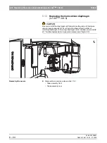
Removing the diaphragm unit
z
Remove the diaphragm unit
(see section 6.12).
Removing the defective tube assembly
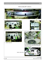
1.
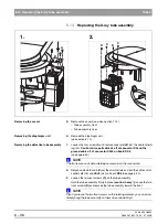
Loosen the four screws
A
and remove cover plate
B
incl. the cable shield-
ing (L3).
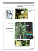
Caution! Also pull cable L3 off of connector X3 and the
ground cable off of connector X304 on board DX6
.
(see page 6-40)
NOTE
i
The ferrite core and cable shielding can remain on the cover plate.
z
Detach cables
L5
and
L6
from the strain reliefs and pull the cables off of
sockets
J6
(L5)
and
J2-J3
(L6) on board
DX6
(see page 6-40).
2.
Loosen the two rear screws
(C)
on the tube assembly.
Hold the tube assembly firmly in place
(caution: heavy!)
, loosen the two
front screws
(D)
and remove the tube assembly toward the front.
NOTE
i
Tip:
If you leave the two front screws on the rotating element, you can imme-
diately hang the tube assembly on them when reinstalling it.
1.
2.
A
B
C
D
C
D
Summary of Contents for ORTHOPHOS XG 3 DS
Page 4: ......
Page 9: ...ORTHOPHOS XG 1General information...
Page 12: ...59 38 399 D3352 1 4 D3352 076 01 13 02 07 2008 Tab1...
Page 59: ...ORTHOPHOS XG 2 Messages...
Page 124: ...59 38 399 D3352 2 66 D3352 076 01 13 02 07 2008 2 6 List of available service routines Tab 2...
Page 125: ...ORTHOPHOS XG 3 Troubleshooting...
Page 153: ...ORTHOPHOS XG 4 Adjustment...
Page 269: ...ORTHOPHOS XG 5 Service routines...
Page 433: ...ORTHOPHOS XG 6 Repair...
Page 436: ...59 38 399 D3352 6 4 D3352 076 01 13 02 07 2008 Tab6...
Page 530: ...59 38 399 D3352 6 98 D3352 076 01 13 02 07 2008 6 21 Replacing cables Tabs 6...
Page 531: ...ORTHOPHOS XG 7 Maintenance...
Page 577: ...b 59 38 399 D3352 D3352 076 01 13 02 07 2008...


