


59 38 399 D3352
5 – 136
D3352.076.01.13.02
07.2008
5.19 Service routine S034
Tabs 5
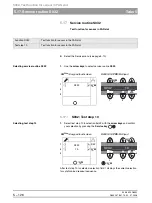
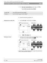
S034.4: Display/calibrate center position of ceph scan sensor axis
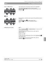
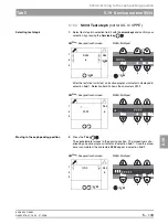
Switching the test mode ON
2.
Press the
T key
to switch the test mode on.
NOTE
i
In the test mode, travel to the center position of the ceph scan sensor axis is
initially performed without offsets. The T key (XG
Plus
) or the LED above the
T key (XG 5) lights up and displays the test mode.
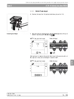
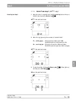
Determining the offset values
3.
Move the sensor to its front position by pressing the
R key
.
NOTE
i
The sensor can always be moved back and forth between its front and center
positions with the R key.
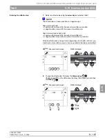
4.
Move the sensor to its center position by pressing the
R key
.
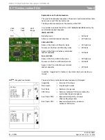
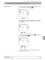
5.
Measure distances
L2
and
L1
with a slide gage.
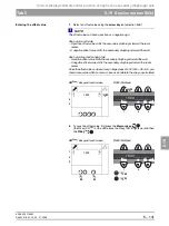
6.
Calculate the offset value according to the following formula:
Ceph arm mounted on left side:
Ceph arm mounted on right side:
T
T
Wall side
Sensor side
Room side
R
R
R
R
L1
L2
Wall side
Room side
L1
L2
Ceph arm mounted on
left-hand side
Ceph arm mounted on
right-hand side
L2
L1
)
2
÷
–
(
Offsetwert
=
L1
L2
)
2
÷
–
(
Offsetwert
=
Summary of Contents for ORTHOPHOS XG 3 DS
Page 4: ......
Page 9: ...ORTHOPHOS XG 1General information...
Page 12: ...59 38 399 D3352 1 4 D3352 076 01 13 02 07 2008 Tab1...
Page 59: ...ORTHOPHOS XG 2 Messages...
Page 124: ...59 38 399 D3352 2 66 D3352 076 01 13 02 07 2008 2 6 List of available service routines Tab 2...
Page 125: ...ORTHOPHOS XG 3 Troubleshooting...
Page 153: ...ORTHOPHOS XG 4 Adjustment...
Page 269: ...ORTHOPHOS XG 5 Service routines...
Page 433: ...ORTHOPHOS XG 6 Repair...
Page 436: ...59 38 399 D3352 6 4 D3352 076 01 13 02 07 2008 Tab6...
Page 530: ...59 38 399 D3352 6 98 D3352 076 01 13 02 07 2008 6 21 Replacing cables Tabs 6...
Page 531: ...ORTHOPHOS XG 7 Maintenance...
Page 577: ...b 59 38 399 D3352 D3352 076 01 13 02 07 2008...