Revised 2017-08-31
Automation Tab
Drawing No. LP0997-C
I/O Settings (RAM-9000 Models)
Sixnet
®
Series SN/RAM
®
6000 & RAM 9000 Software Manual
- 225 -
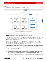
in the Offset display box. Click the Apply button and observe the effect of the new offset factor. Repeat
this step until a satisfactory reading is obtained.
3. Set your analog device for a near full scale (85 to 95% full scale) output. Compare the value currently
being reported with the value on your meter. If they are not equal, adjust the span value by using the
slide bar and arrows in the span display box. Click the Apply button and observe the effect of the new
span factor. Repeat this step unit a satisfactory reading is obtained.
4. The channel is now calibrated.
User Span Correction:
Manually adjust the user span calibration for analog inputs/outputs. Every analog
input/output is calibrated at the factory according to specified accuracy. The user calibration is supplied to
account to adjust the reported values to account for wiring or instrumentation errors. For this reason, most
inputs/outputs will NOT need to be calibrated. Span calibration are used to adjust the reported value from 85 to
95% of full-scale.
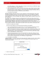
The calibration can be adjusted coarsely by moving the slide bar to the left or right with a mouse. For fine
adjustments, use the -/+ buttons on either side of the slide bar. The corresponding adjustment will be displayed
in the calibration configuration. The calibration will not take effect until the apply button is clicked. A negative
adjustment (negative calibration value) will cause the reported channel value to go down. A positive
adjustment (positive calibration value) will cause the reported channel value to go up. The larger the calibration
value, the greater the difference will be between the reported channel value and the actual measured value.
Instructions on adding user calibration:
Use this method to calibrate a channel using the manual slide bar user calibration:
1. Set your analog signal device for a near minimum (5 to 15% full scale) output. Measure the device’s
output at the module’s screw terminals with a precision meter or external standard monitor.
2. Apply the small signal to the analog input channel. Compare the value currently being reported with the
value on your meter. If they are not equal, adjust the Offset value by using the slide bar and arrows in
the Offset display box. Click the Apply button and observe the effect of the new offset factor. Repeat
this step until a satisfactory reading is obtained.
3. Set your analog signal device for a near full scale (85 to 95% full scale) output. Compare the value
currently being reported with the value on your meter. If they are not equal, adjust the Span value by
using the slide bar and arrows in the Span display box. Click the Apply button and observe the effect of
the new span factor. Repeat this step until a satisfactory reading is displayed.
4. The channel is now calibrated.
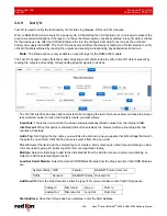
Calibration Wizard:
You will need to measure the analog signal with a reliable instrument in order to calibrate
the module correctly using the calibration wizard. Click on the Calibration Wizard button adjacent to the
channel to start the wizard:
1. Click the Proceed button.

