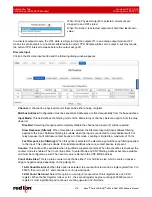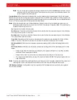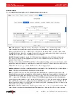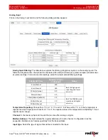
Automation Tab
Revised 2017-08-31
I/O Settings (RAM 6000 Models)
Drawing No. LP0997-C
- 216 -
Sixnet
®
Series SN/RAM
®
6000 & RAM 9000 Software Manual
3.6.7
I/O
Settings
(RAM
6000
Models)
I/O
Control
Click on the
I/O Control
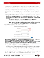
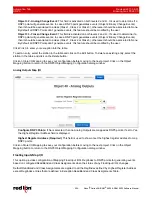
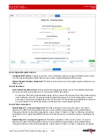
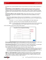
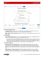
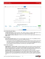
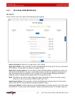
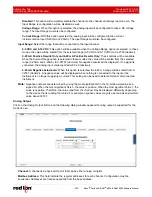
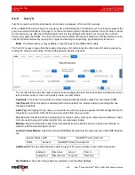
menu item and the following window appears:
Enable this interface:
Select Yes to enable the I/O CTRL Interface.
Digital Input Address:
Enter the address of internal IODB database for Digital Input I/O control. Valid values
for this field are 1 through 65535 as defined for specified I/O type.
Digital Input Counter Address:
Enter the address of internal IODB database for Digital Input Counter. The
valid values for this field are 1 through a value of defined register allocation configured for Analog Input I/O
type. The address ranges are displayed on I/O Transfer screen under ‘Display of Modbus Default Slave
Addresses’ based on configured local register allocation for specified I/O type.
Note:
This address cannot be the same address as Analog Input Address. Take care to select a unique
address to be used in Analog Input IODB for Digital Input Corner.
Digital Output Address:
Enter the address of internal IODB database for Digital Output I/O control. Valid
values for this field are 1 through 65535 as defined for specified I/O type.
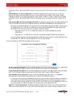
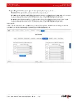
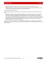
Analog Input Address:
Enter the address of internal IODB database for Analog Input I/O control. Valid values
for this field are 1 through value defined registers configured for specified I/O type. The address ranges are


