Part 2: Review on Replacement of MR-J3-_A_ with MR-J4-_A_
2 - 14
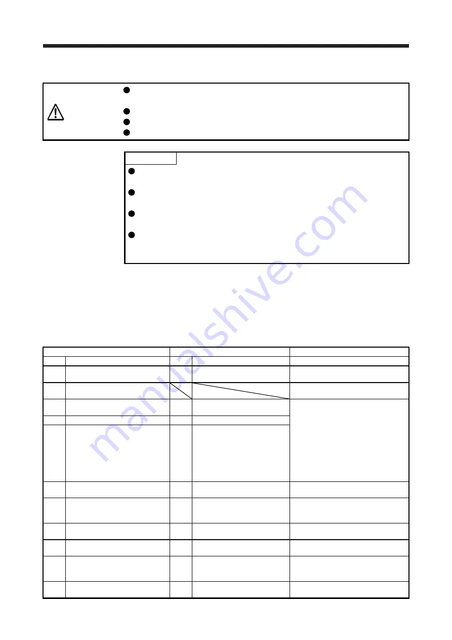
3.5 Comparison of Parameters
CAUTION
Never perform extreme adjustments and changes to the parameters, otherwise
the operation may become unstable.
If fixed values are written in the digits of a parameter, do not change these values.
Do not change parameters for manufacturer setting.
Do not enter any setting value other than those specified for each parameter.
POINT
For the parameter converter function, refer to "Part 6: Common Reference
Material".
To enable a parameter whose abbreviation is preceded by *, turn the power
OFF and then ON after setting the parameter.
For details about parameter settings for replacement, refer to the "MR-J4-_A_
Servo Amplifier Instruction Manual".
With MR-J4-_A_, the deceleration to a stop function is enabled by factory
settings. To disable the deceleration to a stop function, set [Pr. PA04] to "0 _ _
_".
3.5.1 Setting requisite parameters upon replacement
The parameters shown in this section are a minimum number of parameters that need to be set for
simultaneous replacement. Depending on the settings of the currently used amplifier, parameters other than
these may need to be set.
(1) Parameters common to position control mode, speed control mode, and torque control mode
MR-J3-_A_ MR-J4-_A_
Precautions
No. Name No. Name
PA02 Regenerative option
PA02 Regenerative option
The setting value must be changed to use
the regenerative option added for J4-A.
PA04 CN1-23 pin function selection
No corresponding parameter (Can
substitute with PD23 to PD26, PD28.)
PA05 Number of command input pulses
per revolution
PA05 Number of command input pulses
per revolution
The setting value must be changed
according to the encoder resolution.
The setting value must be changed
according to PA21 (Electronic gear
selection).
When J3-A: PA05 = 0
→
J4-A: PA21 = 2_ _ _
(Set the values of PA06 and PA07 for J3.)
When J3-A: PA05 = other than 0
→
J4-A: PA21 = 1_ _ _
PA06 Electronic gear numerator
PA06 Electronic gear numerator
PA07 Electronic gear denominator
PA07 Electronic gear denominator
PA09 Auto tuning response
PA09 Auto tuning response
The setting value must be changed based
on machine resonance frequency.
PB06 Load to motor inertia ratio
PB06 Load to motor inertia ratio
The unit system is different. (0.1 times
→
0.01 times)
Check the setting value.
PB07 Model loop gain
PB07 Model loop gain
The unit system is different. (rad/s
→
0.1
rad/s)
PB08 Position loop gain
PB08 Position loop gain
The unit system is different. (rad/s
→
0.1
rad/s)
PB29 Load to motor inertia ratio after gain
switching
PB29 Load to motor inertia ratio after
gain switching
The unit system is different. (0.1 times
→
0.01 times)
Check the setting value.
PB30 Position loop gain after gain
switching
PB30 Position loop gain after gain
switching
The unit system is different. (rad/s
→
0.1
rad/s)
Summary of Contents for Melservo MR-J3-100B
Page 17: ...8 MEMO ...
Page 18: ...Part 1 Summary of MR J3 MR J3W Replacement 1 1 Part 1 Summary of MR J3 MR J3W Replacement ...
Page 145: ...Part 3 Review on Replacement of MR J3 _B_ with MR J4 _B_ 3 48 MEMO ...
Page 195: ...Part 4 Replacement of MR J3W _B with MR J4W2 _B 4 50 MEMO ...
Page 277: ...Part 5 Review on Replacement of MR J3 DU_ with MR J4 DU_ 5 82 MEMO ...
Page 278: ...Part 6 Common Reference Material 6 1 Part 6 Common Reference Material ...
Page 418: ...Part 7 Review on Replacement of Motor 7 1 Part 7 Review on Replacement of Motor ...
Page 564: ...Part 9 Startup Procedure Manual 9 1 Part 9 Startup Procedure Manual ...
Page 567: ...Part 9 Startup Procedure Manual 9 4 MEMO ...
Page 589: ...L NA 03127ENG C ...


