Part 4: Replacement of MR-J3W-_B with MR-J4W2-_B
4 - 32
MR-J3W-_B MR-J4W2-_B
No.
Name and function
Initial
value
No.
Name and function
Initial
value
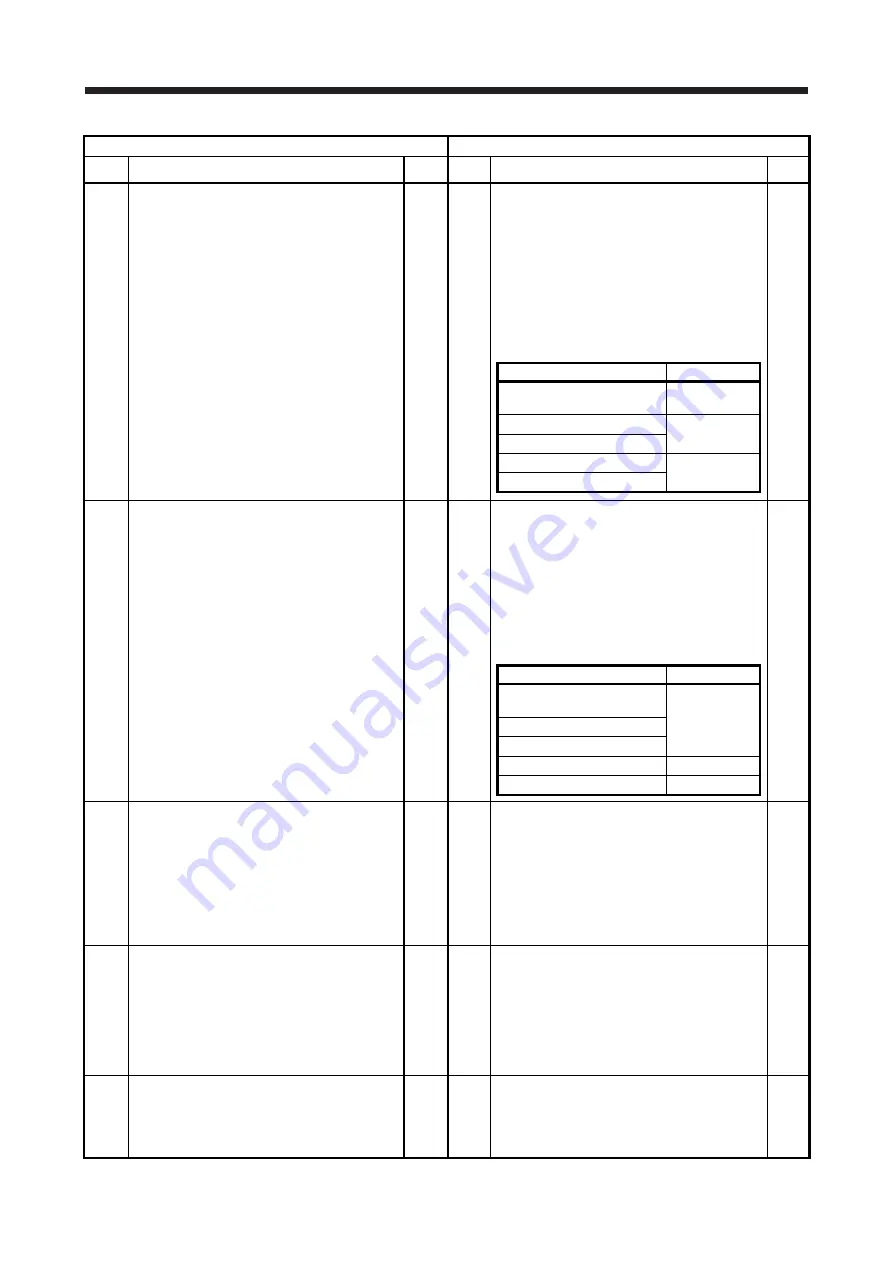
PB07 Model loop gain
Set the response gain up to the target position.
Increase the gain to improve track ability in response to
the command.
When auto turning mode 1, 2 is selected, the result of
auto turning is automatically used.
When [Pr. PA08] is set to "_ _ _ 0" or "_ _ _ 3" , this
parameter can be set manually.
24
PB07 Model loop gain
Set the response gain up to the target position.
Increasing the setting value will also increase the
response level to the position command but will be liable
to generate vibration and noise.
For the vibration suppression control tuning mode, the
setting range of [Pr. PB07] is limited. Refer to "MR-
J4W2-_B servo amplifier instruction manual" for details.
The setting of the parameter will be the automatic setting
or manual setting depending on the [Pr. PA08] setting.
Refer to the following table for details.
Pr. PA08
This parameter
_ _ _ 0 (2 gain adjustment mode 1
(interpolation mode))
Manual setting
_ _ _ 1 (Auto tuning mode 1)
Automatic setting
_ _ _ 2 (Auto tuning mode 2)
_ _ _ 3 (Manual mode)
Manual setting
_ _ _ 4 (2 gain adjustment mode 2)
15.0
PB08 Position loop gain
This parameter cannot be used in the speed control
mode.
Used to set the gain of the position loop.
Set this parameter to increase the position response to
level load disturbance. Higher setting increases the
response level but is liable to generate vibration and/or
noise.
When auto tuning mode 1, 2 and interpolation mode is
selected, the result of auto tuning is automatically used.
When [Pr. PA08] is set to " _ _ _ 3", this parameter can
be set manually.
37
PB08 Position loop gain
Set a gain of the position loop.
Set this parameter to increase the position response to
level load disturbance.
Increasing the setting value will also increase the
response level to the load disturbance but will be liable to
generate vibration and noise.
The setting of the parameter will be the automatic setting
or manual setting depending on the [Pr. PA08] setting.
Refer to the following table for details.
Pr. PA08
This parameter
_ _ _ 0 (2 gain adjustment mode 1
(interpolation mode))
Automatic setting
_ _ _ 1 (Auto tuning mode 1)
_ _ _ 2 (Auto tuning mode 2)
_ _ _ 3 (Manual mode)
Manual setting
_ _ _ 4 (2 gain adjustment mode 2)
Automatic setting
37.0
PB09
Speed loop gain
Set this parameter when vibration occurs on machines of
low rigidity or large backlash.
Higher setting increases the response level but is liable
to generate vibration and/or noise.
When auto tuning mode 1, 2 and interpolation mode is
selected, the result of auto tuning is automatically used.
When [Pr. PA08] is set to " _ _ _ 3", this parameter can
be set manually.
823
PB09 Speed loop gain
Set a gain of the speed loop.
Set this parameter when vibration occurs on machines of
low rigidity or large backlash. Increasing the setting value
will also increase the response level but will be liable to
generate vibration and noise.
The setting of the parameter will be the automatic setting
or manual setting depending on the [Pr. PA08] setting.
Refer to the table of [Pr. PB08] for details.
823
PB10 Speed integral compensation
Used to set the integral time constant of the speed loop.
Lower setting increases the response level but is liable
to generate vibration and/or noise.
When auto tuning mode 1, 2 and interpolation mode is
selected, the result of auto tuning is automatically used.
When [Pr. PA08] is set to " _ _ _ 3", this parameter can
be set manually.
33.7
PB10
Speed integral compensation
Set an integral time constant of the speed loop.
Decreasing the setting value will increase the response
level but will be liable to generate vibration and noise.
The setting of the parameter will be the automatic setting
or manual setting depending on the [Pr. PA08] setting.
Refer to the table of [Pr. PB08] for details.
33.7
PB11 Speed differential compensation
Used to set the differential compensation.
When [Pr. PB24] is set to "_ _ 3_" , this parameter is
made valid. When [Pr. PB24] is set to "_ _ 0_", this
parameter is made valid by instructions of controller.
980
PB11 Speed differential compensation
Set a differential compensation.
To enable the parameter, select "Continuous PID control
enabled (_ _ 3 _)" of "PI-PID switching control selection"
in [Pr. PB24].
980
Summary of Contents for Melservo MR-J3-100B
Page 17: ...8 MEMO ...
Page 18: ...Part 1 Summary of MR J3 MR J3W Replacement 1 1 Part 1 Summary of MR J3 MR J3W Replacement ...
Page 145: ...Part 3 Review on Replacement of MR J3 _B_ with MR J4 _B_ 3 48 MEMO ...
Page 195: ...Part 4 Replacement of MR J3W _B with MR J4W2 _B 4 50 MEMO ...
Page 277: ...Part 5 Review on Replacement of MR J3 DU_ with MR J4 DU_ 5 82 MEMO ...
Page 278: ...Part 6 Common Reference Material 6 1 Part 6 Common Reference Material ...
Page 418: ...Part 7 Review on Replacement of Motor 7 1 Part 7 Review on Replacement of Motor ...
Page 564: ...Part 9 Startup Procedure Manual 9 1 Part 9 Startup Procedure Manual ...
Page 567: ...Part 9 Startup Procedure Manual 9 4 MEMO ...
Page 589: ...L NA 03127ENG C ...


