8-58
Drive Functions
MPH-02, MPB-02, MPD-02
DOK-INDRV*-MP*-02VRS**-FK01-EN-P
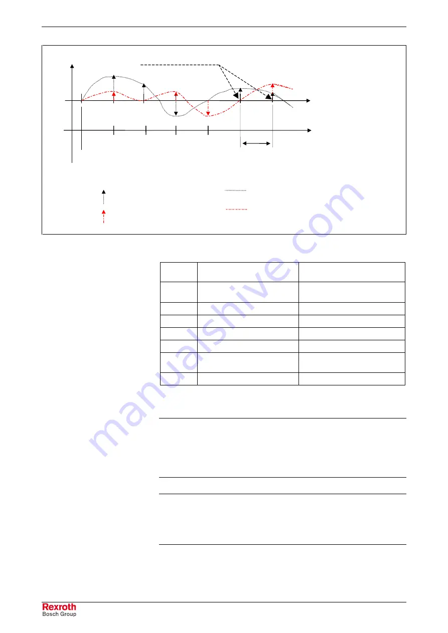
start position
(P-0-0408)
support point distance
(P-0-0410)
correction value
actual position
value uncorrected
correction value curve, interpolated
(positive direction of motion)
correction value curve, interpolated
(negative direction of motion)
0
3
1
4
6
5
2
table index of
P-0-0411, P-0-0412
max. 499
.......
example of corr. supp.
points, (equidistant)
correction value at support point
(positive direction of motion)
correction value at support point
(negative direction of motion)
Legend:
Fig. 8-37:
Illustration of correction value generation from the entered correction
support points
Table
index
P-0-0411
(positive direction)
P-0-0412
(negative direction)
0
0 (correction value at start
position P-0-0408)
0 (correction value at start
position P-0-0408)
1
correction value support point 2 correction value support point 2
2
correction value support point 3 correction value support point 3
3
correction value support point 4 correction value support point 4
....
....
....
498
correction value support point
499
correction value support point
499
499
0
0
Fig. 8-38:
Assignment of support point correction values to table index of
correction tables P-0-0411 and P-0-0412
Note:
It is not necessary to use all 500 table values. It is
recommended, however, to use the same number of
correction support points for positive and negative directions of
motion! The first and the last correction value of the table have
to be zero in order to avoid discontinuity (abrupt changes) in
the actual position value!
Note:
Different correction values for positive and negative directions
of motion at the same support point are causing discontinuity
in the corresponding actual position value upon a change in
direction and therefore are possibly causing abrupt control with
regard to the command position!
Courtesy
of
CMA/Flodyne/Hydradyne
▪
Motion
Control
▪
Hydraulic
▪
Pneumatic
▪
Electrical
▪
Mechanical
▪
(800)
426-5480
▪
www.cmafh.com


