7-86
Operating Modes
MPH-02, MPB-02, MPD-02
DOK-INDRV*-MP*-02VRS**-FK01-EN-P
Actual position value of measuring encoder
with
P-0-0054,
Additive master axis position
and
S-0-0048, Position command
value additional
must be within the max. travel range after conversion
to the internal format.
Note:
Incorrect parameterization can cause unwanted jumps in
position.
Recommendation: activate position limit value monitor!
See "Limitations: Position Limitation" in chapter "Drive Control"
The synchronization distance is calculated according to the following
formula:
value
position
actual
S
XSynch
−
−
−
+
=
0048
0
distance
Fig. 7-64:
Synchronization distance with absolute scaling
The synchronization range corresponds to the max. travel range.
Dynamic Synchronization with Velocity Synchronization
Drive-controlled dynamic synchronization in the "velocity synchronization"
mode is carried out depending on bit 5 of parameter P-0-0155.
P-0-0155, Synchronization mode
:
•
bit 5 = 0
→
synchronization only takes place when the operating
mode is activated
•
bit 5 = 1
→
synchronization is always active
By generating velocity command values, the drive accelerates or
decelerates during synchronization until the synchronous velocity has
been reached. The velocity command values are generated in
consideration of
P-0-0142, Synchronization acceleration
.
P-0-0048
dynam.
synchron-
ization
P-0-0142
P-0-0155
P-0-0152
DF000099v01_en.fh7
internal
command
value
electronic
gear
with
fine adjust
master axis
evaluation
and
adjustment
cmd value
processing
specific to
oper. mode
P-0-0775
Dynamic synchronization
+
Fig.
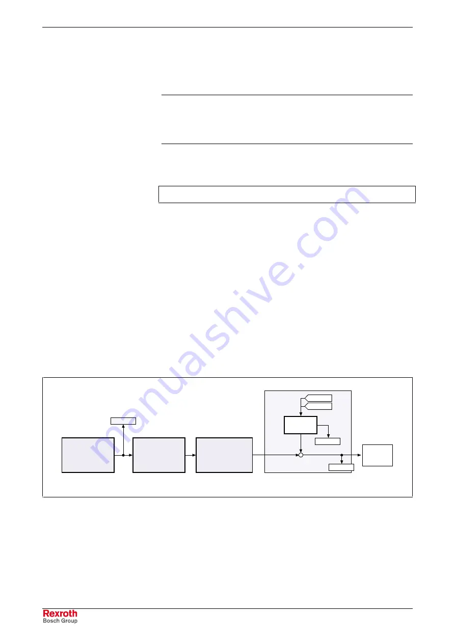
7-65:
Function block "dynamic synchronization" for velocity
synchronization
•
synchronization takes place as velocity adjustment
•
generation of status message "synchronization completed" (P-0-0152;
bit 0)
•
generation of status message "synchronization mode in
synchronization" (P-0-0089; bit 8)
Features
Courtesy
of
CMA/Flodyne/Hydradyne
▪
Motion
Control
▪
Hydraulic
▪
Pneumatic
▪
Electrical
▪
Mechanical
▪
(800)
426-5480
▪
www.cmafh.com


