8-14
Drive Functions
MPH-02, MPB-02, MPD-02
DOK-INDRV*-MP*-02VRS**-FK01-EN-P
DF0072v1.fh7
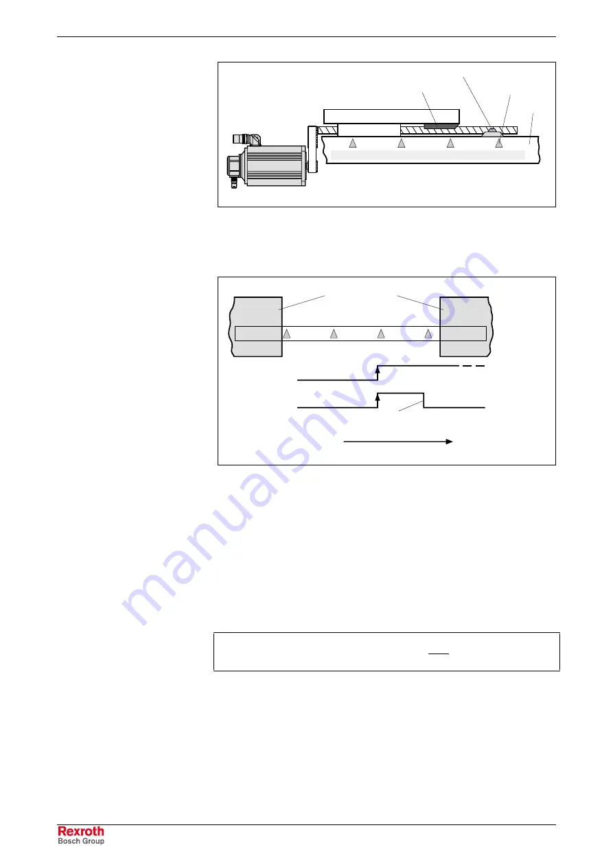
mapped reference marks of motor encoder
axis slide
switch cam
home switch
axis
selected
reference mark
Fig. 8-9:
Selecting a reference mark via home switch
After starting the C0600 command, the dedicated point is detected when
the first reference mark signal occurs after the determined edge of the
home switch.
DF0075v1.fh7
reference travel direction
correct implementation of "activated" range
of home switch signal
incorrect implementation of "activated" range
of home switch signal
travel range limits
Fig. 8-10:
Arranging the home switch with regard to travel range limits
In the case of linear axes, the "activated" range of the home switch has to
reach beyond the next travel range limit. The home switch signal thereby
indicates the proximity of the end of the travel range if the reference travel
direction was appropriately selected. The travel range limit is not passed
during the homing procedure when the "activated" range of the home
switch signal begins with sufficient distance to the travel range limit!
The distance between dedicated point (first reference mark after home
switch signal) and travel range limit is sufficient if the drive can safely
shutdown the axis out of maximum homing velocity (S-0-0041) with
homing acceleration (S-0-0042), within the travel range. The following
applies to the minimum distance home switch-travel range limit:
a
*
2
v
x
x
2
RefMarks
HS_TrLimit
+
≥
v:
value in S-0-0041, Homing velocity
a:
value in S-0-0042, Homing acceleration
x
RefMarks
:
distance of the reference marks occurred at the axis - or –
value of S-0-0165 for distance-coded measuring system
x
HS_TrLimit
:
minimum distance to travel range limit
Fig. 8-11:
Minimum distance of home switch signal to travel range limit
Arranging the Home Switch
Courtesy
of
CMA/Flodyne/Hydradyne
▪
Motion
Control
▪
Hydraulic
▪
Pneumatic
▪
Electrical
▪
Mechanical
▪
(800)
426-5480
▪
www.cmafh.com


