8-48
Drive Functions
MPH-02, MPB-02, MPD-02
DOK-INDRV*-MP*-02VRS**-FK01-EN-P
8.5 Compensation
Functions/Corrections
Friction Torque Compensation
Brief Description
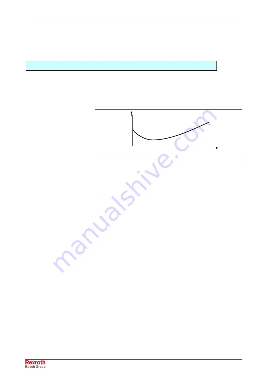
The behavior of a machine axis is negatively affected by static friction
when starting or when reversing the direction. The drive-internal friction
torque compensation allows compensating the static friction by adding,
depending on the direction of movement, a torque/force command value.
DK0017v1.fh7
static
friction
v
M
frict
Fig. 8-28:
Friction torque curve with static friction
Note:
Friction torque compensation is mainly intended to be used in
precision machine tools and to reduce the path errors caused
by static friction. This applies particularly to circular errors at
the quadrant transitions.
Pertinent Parameters
•
S-0-0092, Bipolar torque/force limit value
•
S-0-0124, Standstill window
•
S-0-0155, Friction compensation
Operating Principle
The principle of friction torque compensation is that the known friction
component is pre-controlled (compensated) via an added torque/force
command value and does not have to be compensated by the controller.
This allows, especially when reversing the direction of movement,
improving the control behavior (little lag error). Precision of drive control is
thereby increased.
Expansion package
servo function
(order code
SRV
) with
closed-loop
characteristic
Courtesy
of
CMA/Flodyne/Hydradyne
▪
Motion
Control
▪
Hydraulic
▪
Pneumatic
▪
Electrical
▪
Mechanical
▪
(800)
426-5480
▪
www.cmafh.com


