7-72
Operating Modes
MPH-02, MPB-02, MPD-02
DOK-INDRV*-MP*-02VRS**-FK01-EN-P
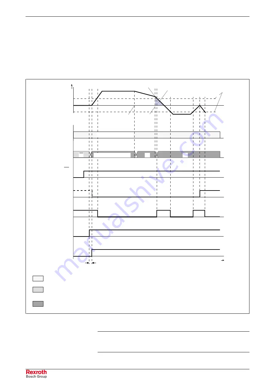
Block n with intermediate stop follows block n-1 with mode 1 (block
transition with old positioning velocity), because a change in direction
occurs when changing from block n to block n+1. At change in direction
there is a change of sign of the velocity at target position n. If the
acceleration parameterized in block n is too low to decelerate within the
path difference x
n
-x
n-1
from velocity v
n-1
to the value "0", the parameterized
target position x
n
will be overrun.
This may cause software or hardware limit switches to trigger.
v
01
DK000038v01_en.fh7
positioning block
acceptance:
P-0-4060 (bit 0)
t
S-0-0419,
Positioning command
acknowledge
end position reached:
P-0-4061,
Positioning block
status word (bit 4)
P-0-4051,
Positioning block
acknowledgment
P-0-4026,
Positioning block
selection
velocity
profile
03
positioning inputs valid
positioning acknowledgment outputs show negated status
of positioning inputs
after valid block acceptance, positioning acknowledgment outputs
show non-inverted status of positioning inputs
t
R
positioning block 01
S-0-0124,
Standstill
window
in standstill:
S-0-0013,
Class 3
diagnostics (bit 1)
positioning block 01
x = 600
02
area corresponding to dis-
tance by which target posi-
tion of block n is passed
target position
is passed
target
position
block n-1
target
position
block n
target
position
block n+1
Drive HALT (AH):
S-0-0134,
Master control
word (bit 13)
Fig. 7-43:
Parameterizing a sequential block with directional change
Note:
According to master communication, positioning block
acceptance takes place by toggling bit 0 in S-0-0346 or by a 0-
1 edge of bit 0 in P-0-4060.
Explanation of the Figure Below
Courtesy
of
CMA/Flodyne/Hydradyne
▪
Motion
Control
▪
Hydraulic
▪
Pneumatic
▪
Electrical
▪
Mechanical
▪
(800)
426-5480
▪
www.cmafh.com


