Chapter 4 Operation and Display
-68-
F5 -00
F5 -01
F5 -02
F5 -03
F5 -04
.
.
.
.
.
15
14
13
12
..
0 0 0 0
0 0 0 1
0 0 1 0
. .
1 1 1 0
1 1 1 1
FC - 00
FC - 01
FC - 02
..
FC -14
FC -15
0
1
DI1
DI2
DI3
DI4
DI5
0
0
P0-06=4
P5-00
P5-01
P5-02
P5-03
P5-04
P0 10=0
PC-00
PC-01
PC-02
..
PC-14
PC-15
Port
Function
code
Set
value
(
binary) state
combination
Multi-segment
frequency table %
Select multi-segment
frequency as
frequency source
-
Frequency
source selection
target
operating
frequency
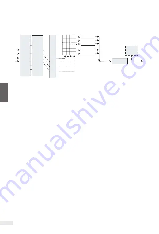
Figure 4-21
Schematic diagram of multi-speed control
In the figure above, DI2, DI3, DI4, and DI5 are selected as the signal input termin-
als for multi-segment frequency designation, and 4-bit binary numbers are formed
from them in turn, and the multi-segment frequency is selected by combining the
values according to the state. When (DI5, DI4, DI3, DI2) = (0, 0, 1, 0), the number
of state combinations formed is 2, and the frequency set by the PC-02 function
code will be selected as the target operating frequency.
KD600 can set up to 4 DI ports as multi-segment frequency command input term-
inals, and also allow less than 4 DI ports to perform multi-segment frequency set-
ting. For the missing setting bits, it is always calculated as state 0.
After the inverter restores the factory parameters, press the "RUN" key, the invert-
er drives the motor's direction, which is called the forward direction. If the rotation
direction at this time is opposite to the direction required by the equipment, please
set P0-13=1 or power off. After that (pay attention to the discharge of the main
capacitor charge of the inverter), replace any two wirings in the UVW output line
of the inverter to eliminate the problem of the rotation direction.
In some drive systems, only the system is allowed to run in the forward direction
and not in the reverse direction, you need to set P0-13 = 2. If there is a reverse
command at this time, the inverter will decelerate to 0 and enter the stop state,
and at the same time FWD/REV keeps flashing on the operation panel. The logic
shown in the figure below.
4.7.6 Motor running direction setting
C
h
a
p
te
r
4
Summary of Contents for 2S-0.4G-B
Page 6: ...Safety and Attentions Chapter 1 1 1 Safety Matters 6 1 2 Use Considerations 9...
Page 80: ...Function Parameter Table 5 1 Functional group 78 Chapter 5...
Page 126: ...Function Parameter Table Chapter 6...
Page 245: ......
Page 249: ......
Page 255: ......


