


8-38
SRW-5000/5500
A
8-9. Tele-File System Adjustment
(DIO-69 Board)
m
.
Perform this adjustment when the DIO-69 or SE-606A
board has been replaced.
.
For detail of each menu in the maintenance mode, refer
to Section 3.
Tools
.
Oscilloscope:
TEKTRONIX TDS3054B or equivalent
n
Use a probe with input capacity of approx. 10.8 pF
(TEK P6137 or equivalent).
.
Adjusting driver (ceramic)
.
Recording tape: BCT-SR series
n
The HDCAM cassette tape with the Tele-File label can
be used for adjustment/check.
Adjustment
n
Pay careful attention to the following points to perform the
correct adjustment.
.
Be sure to remove the cassette tape from the unit.
.
Keep the SE-606A board away from the piece of metal
such as chassis and so on.
1.
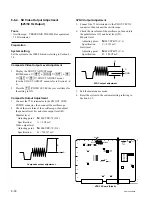
Set and connect the oscilloscope as follows:
n
Never contact the ground probes with the DIO-69
board. This may cause damage to the circuit on the
DIO-69 board.
CH-1: TP101/DIO-69 (A-2), AC 5 V/DIV
GND: Chassis
CH-2: TP102/DIO-69 (A-2), AC 5 V/DIV
GND: Chassis
MODE: CH2 INVERT, ADD,
20 MHz BW LIMIT = OFF
TIME: 20 nsec/DIV
TRIG: CH-1, AC
LEVEL: 1 V
2.
Turn on the power, and display the Tele-File CHECK
menu.
(HOME menu
→
[SFT]
+
[DIAG]
→
[SFT]
+
[F8]
→
[F9]
→
[F1]
→
Tele-File CHECK menu)
(For the Tele-File CHECK menu, refer to Section 3-3-9.)
3.
Press the
[F2]
(RF) key to the setting to ON.
4.
While checking the 13.5 MHz waveform with the
oscilloscope, adjust using the adjusting driver (ceram-
ic) to maximize the amplitude.
Adj. point:
1
CT101/DIO-69 (A-2)
Specification: A = maximum value (more than 14 V
p-p of sine waveform)
5.
Insert the recording tape.
6.
Press the
[F3]
(READ TEST) key.
7.
Check that the FAIL is 0 after 10 seconds.
8.
Press the
[F4]
(WRITE TEST) key.
9.
Press the
[F4]
(WRITE TEST) key while pressing the
[SFT]
(SHIFT) key.
10. Check that the FAIL is 0 after 10 seconds.
11. Exit the maintenance mode.
12. Eject the recording tape.
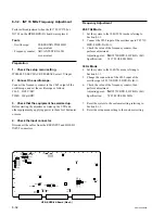
DIO-69 Board (Side A)
TP101
TP102
TP103
TP104
TP105
TP106
CT101
A
B
1
2
3
4