


3-37
SRW-5000/5500
DCP
TEST
VIDEO
TST SG
EXIT
DCP TEST : OFF
VIDEO TEST SG : OFF
AUDIO TEST SG : OFF
SD OUTPUT CHECK
AUDIO
TST SG
OFF
Silence
1kHz SINE
DIAG
F1
F2
F4
ALT
F5
F6
F7
F8
F9
F10
F3
DCP
TEST
VIDEO
TST SG
EXIT
DCP TEST : OFF
VIDEO TEST SG : OFF
AUDIO TEST SG : OFF
SD OUTPUT CHECK
AUDIO
TST SG
OFF RAMP
COLOR BARS BLACK
MULTI BURST WHITE(100%)
10 STEPS PATHOLOGICAL
PULSE & BAR
DIAG
F1
F3
F4
ALT
F5
F6
F7
F8
F9
F10
F2
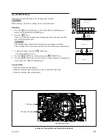
[F3]
(AUDIO TST SG) Key
Selects a signal to be generated from the built-in audio test
signal generator of this unit.
Execution Procedure
On the SD OUT CHECK menu, press the
[F3]
(AUDIO
TST SG) key several times to select the audio test signal.
OFF:
The audio test signal generator stops the
operation.
Other than OFF: The audio test signal generator outputs a
selected signal (below).
Silence
1 kHz SINE
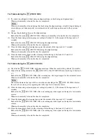
[F2]
(VIDEO TST SG) Key
Select a test signal for the operation check of the down
converter to be generated from the built-in video test signal
generator on this unit.
Execution Procedure
On the SD OUT CHECK menu, press the
[F2]
(VIDEO
TST SG) key several times to select the SD video test
signal.
OFF:
The video test signal generator stops the
operation.
Other than OFF: The video test signal generator outputs a
selected signal (below).
(Also refer to Section 1-23.)
SD video test signal
COLOR BARS
MULTI BURST
10 STEPS
PULSE & BAR
RAMP
BLACK
WHITE (100 %)
PATHOLOGICAL
n
The signals output from the test signal generator can be
recorded on a tape; however, the PATHOLOGICAL is not
recordable on a tape because it is a transmission test signal
output from the SD SDI and is generated from the output
circuit of this unit.