


5-117
SRW-5000/5500
BVTT3
x
6
BVTT3
x
6
BVTT
3
x
6
FP bracket
FP fixed plate
FP-132 board
FP-131 board
BVTT3
x
6
FP fixed plate assembly
Connecting cable
MB-964 board
Guides
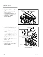
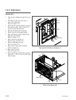
Remove the FP Fixed Plate Assembly
Remove the FP-131/132 Board
5-30-11. FP-131/132 Board
Replacement
1.
Turn the power off and disconnect the power
cord.
2.
Remove the upper lid (front) assembly.
(Refer to Section 1-3-1.)
3.
Remove the power supply unit.
(Refer to Section 5-24.)
4.
Disconnect the DIO-69 board.
(Refer to Section 5-30-8.)
5.
Open the lower control panel.
(Refer to Section 1-6.)
6.
Disconnect the connecting cable of the
control panel.
7.
Remove the two screws fixing the FP fixed
plate assembly.
8.
Disconnect the connector on the MB-964
board to pull out the FP fixed plate assembly
from the chassis.
9.
Remove the two screws (A) to remove the
FP-132 board.
10. Remove the four screws (B) to remove the FP
bracket and the FP fixed plate.
11. Perform the installation in the reverse order
from steps 2 to 10.
Steps after Replacement
12. After replacing the FP-131 or FP-132 board,
check the operation of the board.
(Refer to Section 1-25-14 or 1-25-15.)