


5-84
SRW-5000/5500
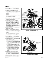
Cassette compartment
motor
CL-29 board
Connector
(CN935)
Connector
Harness
*
Label
Spacer
Claws
Hole
Hub
Boss
*
Hooks
Worm (grease applying)
Hole
Boss
Worm
Spacer
Motor joint
Cassette compartment motor
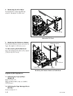
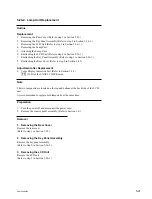
8. Attaching the Spacer and Worm
(1) Fit the boss of the spacer in the hole of the
motor.
(2) Insert the worm to with the motor joint.
(3) Wipe the grease on the worm and clean it.
9. Attaching the Cassette Compartment
Motor
(1) Position the motor as shown in the figure and
pass the harness through the hole of the
chassis.
(2) Match the
*
marked portion of the motor
with the
*
marked portion of the chassis and
fit the motor in the two claws while inserting
the hole of the spacer into the boss of the
chassis. Simultaneously, fit the hub of the
worm in the two claws of the chassis.
(3) Confirm that the motor has been fixed.
10. Applying the Grease
Slightly apply the grease to the worm.
11. Reconnecting the Harness
Reconnect the harness of the cassette comport-
ment motor to the connector CN935 on the CL-29
board.
Adjustment after Replacement
12. Checking the Cassette Compartment
Motor Operation
Refer to Section 3-3-4.
[F8]
(CCM MOTOR) of the SERVO CHECK
menu
n
Perform this check with the cassette compartment
installed in the unit.
Attach the Spacer and Warm
Attach the Cassette Compartment Motor