


5-108
SRW-5000/5500
PSW3
x
8
PSW
3
x
8
BVTT3
x
6
CP-378 board
Connector screws
Connector screws
(RS232C)
Connector panel
assembly
Lug terminal
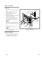
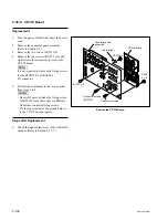
Remove the CP-378 Board
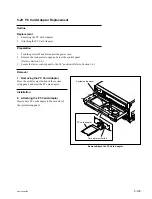
5-30-5. CP-378 Board
Replacement
1.
Turn the power off and disconnect the power
cord.
2.
Remove the connector panel assembly.
(Refer to Section 1-4.)
3.
Remove the two screws (PSW3
x
8).
4.
Remove the four screws (BVTT3
x
6) and
eight screws for connectors to remove the
CP-378 board.
n
It is not required to remove the fixing screws
for the REMOTE-2 PARALLEL
I/O connector.
5.
Perform the attachment in the reverse order
from steps 2 to 4.
m
.
Be careful not to mistake the fixing screws
for RS232C since these only are different
from other connector fixing screws.
.
Fix the rug terminal of the ground harness
to the CP-378 board properly.
Steps after Replacement
6.
Check the input/output level of the AES/EBU
channel. (Refer to Section 1-25-7.)