


5-93
SRW-5000/5500
Installation
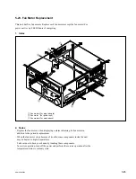
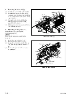
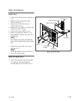
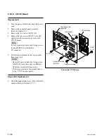
3. Attaching the Dial Assembly
(1) Check that the mode selection plate position
of a new dial assembly is set as shown in the
figure.
If the mode selection plate is NG, loosen the
screw shown in the figure, and then tighten
the screw after sliding the mode selection
plate in the arrow direction A.
(2) Fix a new dial assembly to the key panel
frame with three screws.
Tightening torque: 50
x
10
_
2
N
.
m
{5.0 kgf
.
cm}
(3) Reattach the dial knob to the dial assembly
with the screw.
Tightening torque: 53
x
10
_
2
N
.
m
{5.5 kgf
.
cm}
(4) Reattach the dial knob rubber to the dial
knob.
(5) Connect the harness to the dial assembly.
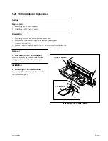
4. Reattaching the Rear Cover
Reattach the rear cover to the key panel frame,
then fix it with eight screws.
Tightening torque:
80
x
10
_
2
N
.
m
{8.0 kgf
.
cm}
Adjustment after Replacement
5. Confirming the Search Dial Operation
Refer to Section 3-3-3.
[F1]
(DIAL) of the PANEL CHECK menu
OK
NG
A
Screw
Mode selection plate
Attach the Dial Assembly
Rear cover
Dial assembly
Dial knob
Dial knob rubber
Key panel frame
B3
x
6
B3
x
6
BVTP3
x
8
PSW2.6
x
5
Check the Mode Selection Plate