


8-1
SRW-5000/5500
Section 8
Electrical Alignment
8-1. Electrical Alignment Overview
8-1-1. Precautions
.
Be sure to adjust each block in order unless any instructions are provided.
.
Do not contact with adjusting part when other than required.
.
Do not execute automatic adjustment, and do not change adjustment data when other than required.
In case either of these is done unintentionally, do not save the data. To recover it, turn off the power of
the VTR .
.
For details on the maintenance mode, refer to Section 3.
.
Before beginning adjustment, it is recommended to make a copy of setup conditions. If customer
conditions are noted, the settings can be returned easily to its customer condition after finishing adjust-
ment.
Settings of switches on panels, circuit boards:
Use the setting check sheets. (Refer to the installation manual.)
Settings of the setup menu:
Use a Memory Stick or memory card. (Refer to “1-26. Memory Stick (or Memory Card)”.)
8-1-2. Outline of Electrical Alignment
In Section 8 explains the all electrical adjustment to each block.
Block
Reference
Contents
Object of adjustment
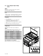
Power supply unit
Section 8-2
Output voltage check of power supply unit
———
Servo/DT
Section 8-3
Servo system and DT system alignment
DT-47, DR-508, SS-95
RF
Section 8-4
RF system alignment
EQ-94
Audio
Section 8-5
Adjustment of Analog audio output line
APR-62
CUE
Section 8-5
Adjustment of CUE line
AE-31H, CUE-13
SD Video
Section 8-6
SD SDI free-running frequency adjustment
VPR-79
Adjustments of Analog composite Video output
HD Video
Section 8-7
HD Video system adjustment
HPR-8/HPR-8A
Full erase, Time code
Section 8-8
LTC system adjustment/check and Full erasure current check
TC-104
Tele-File
Section 8-9
Tele-File system adjustment
DIO-69