


6-31
SRW-5000/5500
Adjustment
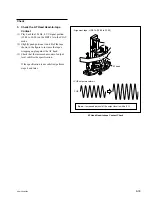
3. Adjust the AT Head Azimuth
(1) Play back the 12 kHz, 0 VU signal portion
(15:00 to 30:00) on the HR2-1A in the PLAY
mode.
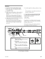
(2) Turn the azimuth adjustment screw so that
the output waveform level becomes maxi-
mum.
(3) Lightly strike the portions A and B shown in
the figure with the tip of a screwdriver. Then
check that the output waveform level is
maximum.
After the Adjustment
4. Adjust the AT Head Head-to-tape
Contact
Refer to Section 6-9.
5. Adjust the AT Head Position
Refer to Section 6-10.
6. Check the AT Head Height
Refer to Section 6-7.
7. Apply the Locking Compound
Refer to Section 6-1-9.
AT Head Azimuth Adjustment
<CUE output waveform>
.
Alignment tape : HR2-1A (15:00 to 30:00)
Azimuth adjustment screw
Height adjustment
screw
Portion A
Portion B
AT head
Maximize