


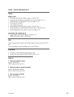


5-95
SRW-5000/5500
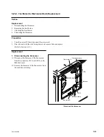
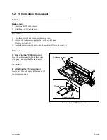
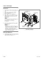
Key panel frame
Spacers
LCD unit
K2
x
6
K2
x
6
Spacers
LCD cover assembly
Remove/Attach the LCD Unit
Replace the LCD Unit
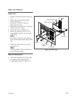
LCD unit
LCD unit
CN1
CN2
CN3
LCD shield case
CP-382 board
CN-2511 board
CN-2511 board
Inverter unit
3. Removing the LCD Unit
(1) Remove the four screws and remove the LCD
unit.
n
Be careful not to lose the screws and spacers
to be removed.
(2) Disconnect the harnesses from the connectors
CN2, CN3 on the inverter unit.
(3) Disconnect the CN-2511 board from the
connector CN1 on the LCD unit.
(4) Remove the LCD shield case from the LCD
unit.
Installation
4. Attaching the LCD Unit
(1) Reattach the LCD shield case to a new LCD
unit.
(2) Connect the CN-2511 board to the connector
CN1 on the LCD unit.
(3) Connect the harnesses of the LCD unit to the
connectors CN2, CN3 on the inverter unit.
(4) Reattach the LCD unit, spacers, and LCD
cover assembly to the key panel frame, then
fix it with four screws. (Refer to the figure in
step 2.)
Tightening torque: 20
x
10
_
2
N
.
m
{2.0 kgf
.
cm}
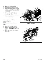
5. Reattaching the Key Panel Assembly
Refer to the figure in the previous page.
(1) Connect the flexible card wire to the connec-
tor CN1 on the KY-526 board.
(2) Reattach the key panel assembly to the key
panel frame, then fix it with eight screws.
Tightening torque: 80
x
10
_
2
N
.
m
{8.0 kgf
.
cm}
(3) Reattach the MULTI CONTROL knob.