


5-97
SRW-5000/5500
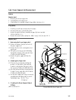
5-26-2. Lamp Unit Replacement
Outline
Replacement
1.
Removing the Rear Cover (Refer to step 1 in Section 5-25.)
2.
Removing the Key Panel Assembly (Refer to step 2 in Section 5-26-1.)
3.
Removing the LCD Unit (Refer to step 3 in Section 5-26-1.)
4.
Removing the Lamp Unit
5.
Attaching the Lamp Unit
6.
Reattaching the LCD Unit (Refer to step 4 in Section 5-26-1.)
7.
Reattaching the Key Panel Assembly (Refer to step 5 in Section 5-26-1.)
8.
Reattaching the Rear Cover (Refer to step 4 in Section 5-25.)
Adjustment after Replacement
9.
Color Display Indication Test (Refer to Section 3-3-3.)
[F5]
(LCD) of the PANEL CHECK menu
Note
The two lamp units are located on the top and bottom at the back side of the LCD
unit.
It is recommended to replace both lamp units at the same time.
Preparation
1.
Turn the power off and disconnect the power cord.
2.
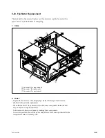
Remove the control panel assembly. (Refer to Section 1-6.)
Removal
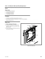
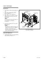
1. Removing the Rear Cover
Remove the rear cover.
(Refer to step 1 in Section 5-25.)
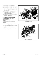
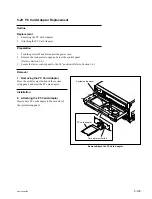
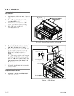
2. Removing the Key Panel Assembly
Remove the key panel assembly.
(Refer to step 2 in Section 5-26-1.)
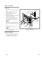
3. Removing the LCD Unit
Remove the LCD unit.
(Refer to step 3 in Section 5-26-1.)