


6-4
SRW-5000/5500
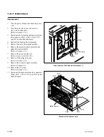
AT head assembly
6-1-7. Preparation
(1) Remove the cassette compartment. (Refer to Section 1-5.)
(2) Remove the video head cleaner assembly. (Refer to Section 5-4.)
n
If the video head cleaner assembly is attached, the tape-running condition may be difficult to check.
Therefore, remove the W cleaner assembly before checking.
(3) Clean the following portions (Refer to Section 4-2):
.
Rotary heads of inner drum (Section 4-2-3)
.
Tape-running surfaces of upper drum (Section 4-2-4)
.
Lower drum’s tape-running surface and lead surface (Section 4-2-5)
.
Stationary heads (Section 4-2-6.)
.
Tape-running system and tape cleaner (Section 4-2-7)
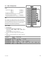
6-1-8. Alignment Tapes
Alignment tapes for adjusting the tape path of each model are listed on the table below.
For the recording descriptions of each alignment tape, refer to Section 1-20.
.
HR2-1A
(Part No. 8-960-076-11)
.
HR2-1B
(Part No. 8-960-076-41)
.
HR5-1A
(Part No. 8-960-076-01)
.
HR5-1B
(Part No. 8-960-076-31)
.
ZR5-1
(Part No. 8-960-073-01)
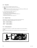
6-1-9. Locking Compound
When loosening the following screws, apply the locking compound to the screws after adjustment is
completed.
The locking compound that applied to other surrounding parts must be wiped off using gauze or soft
cloth.
.
Locking compound : 7-432-114-11