


5-91
SRW-5000/5500
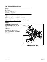
CN100
PSW3
x
8
PSW3
x
8
MB-964 board
Portion B
Portion A
Connector
Harness
Handle
Power supply
installing plate
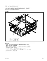
Remove/Attach the Power Supply Unit
5-24. Power Supply Unit Replacement
Outline
Replacement
1.
Removing the Power Supply Unit
2.
Attaching the Power Supply Unit
3.
Checking the Power Supply Output Voltage (Refer to Section 8-2.)
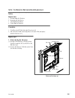
Preparation
1.
Turn the power off and wait more than 30 seconds.
2.
Disconnect the power cord from the outlet.
3.
Remove the upper lid (front) assembly and upper lid (rear) assembly.
(Refer to Section 1-3-1.)
4.
Remove the coaxial cables and bead tie. (Refer to step 1 (2) in Section 5-23-1.)
Replacement
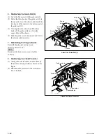
1. Removing the Power Supply Unit
(1) Remove the harness from the connector of
the power supply unit.
(2) Remove the two screws securing the power
supply unit.
(3) Lift up the power supply unit with holding
the handle to disconnect the connector from
CN100 on the MB-964 board.
(4) Remove the power supply unit from the
chassis.
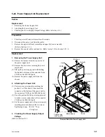
2. Attaching the Power Unit
(1) Put in a new power supply unit along the
portion A’s of the chassis, then insert the
connector at the bottom of the power unit to
the connector CN100 on the MB-964 board.
(2) Press the portion B of the power supply unit
to make a secure connection to the connector
CN100 on the MB-964 board.
(3) Fix the power supply unit to the power supply
installing plate and chassis with two screws.
Tightening torque: 80
x
10
_
2
N
.
m
{8.0 kgf
.
cm}
3. Checking the Power Supply Output
Voltage
(Refer to Section 8-2.)