


6-5
SRW-5000/5500
NG
NG
NG
NG
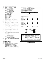
START
1. Set the System
2. Set the Alignment Tape
3. Connect the Oscilloscope
10. System Setting
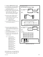
4. Check in the PLAY Mode
5. Check in the REV
x
1 Mode
6. Check in the REV
x
10 Mode
7. Check in the F.FWD and REW Modes
8. Check the ADVANCE Head Contact
9. Check the CONFI Head Output
END
Section 6-3
Section 6-4
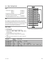
6-2. Video Tracking Check
Tools
.
Alignment tapes HR2-1A:
8-960-076-11
HR2-1B:
8-960-076-41
HR5-1B:
8-960-076-31
.
Recording tape (S cassette):
BCT-40SR
.
Oscilloscope (Tektronix TDS3054B or equivalent)
.
Small mirror for adjustment (Round):
J-6080-029-A
.
Tape guide adjustment screwdriver (MW-261): J-6322-610-A
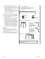
Note
When checking video tracking, the RF envelope waveform (PLAY
mode) should be made flat from the entrance to the exit. However it
may not be completely flat in some cases. For such cases, there should
be no problems only that the specifications are satisfied. Perform
adjustments only when without the specifications.
System Setting
1. Set the System
(1) Turn on the power, and display the SYSTEM menu.
(HOME menu
→
[SFT]
+
[DIAG]
→
[SFT]
+
[F8]
→
[F9]
→
SYSTEM menu)
(For the SYSTEM menu, refer to Section 3-3-9.)
(2) Take notes of the customer settings for the following setting
items.
(3) Change the following setting items to the settings for adjustment.
(59.94i mode)
Video Tracking Check/Adjustment Flow Chart
Setting item
Setting for
Customer setting
adjustment
[F4]
SYSTEM SIGNAL
4:2:2 (YPbPr)
[||]
4:2:2 (YPbPr)
[||]
4:4:4 (RGB)
[F1]
SYSTEM LINE
1080
[||]
1080
[||]
720
[F2]
SYSTEM SCAN
Interlace
[||]
Interlace
[||]
PsF
[||]
Progressive
[F3]
SYSTEM FREQ.
59.94 Hz
[||]
23.98
[||]
24
[||]
25
[||]
29.97
[||]
30
[||]
50
[||]
59.94
[||]
60
[F7]
ACTIVE LINE
1080
[||]
1080
[||]
1035